EURO HEADLIGHTS & HID
 Next on the agenda was to do something
about the terrible lighting that this Mercedes has (hmm, maybe I should say
terrible lighting that all Mercedes have). Of course the logical
course of action was to acquire a set of Euro headlights which I purchased
through www.puma-access.com on a
group purchase for $290. I also picked up a set of gray side markers
which in my opinion are a better match to the euro headlights than the white
side markers. I don't have complete step by step instructions for this
install, but I do have some pictures that can assist you with your own euro
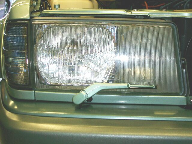
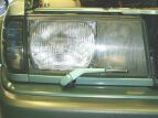
headlight install. This picture here shows the ugly, yellowing factory
headlight that provides little light at night
Next on the agenda was to do something
about the terrible lighting that this Mercedes has (hmm, maybe I should say
terrible lighting that all Mercedes have). Of course the logical
course of action was to acquire a set of Euro headlights which I purchased
through www.puma-access.com on a
group purchase for $290. I also picked up a set of gray side markers
which in my opinion are a better match to the euro headlights than the white
side markers. I don't have complete step by step instructions for this
install, but I do have some pictures that can assist you with your own euro
headlight install. This picture here shows the ugly, yellowing factory
headlight that provides little light at night
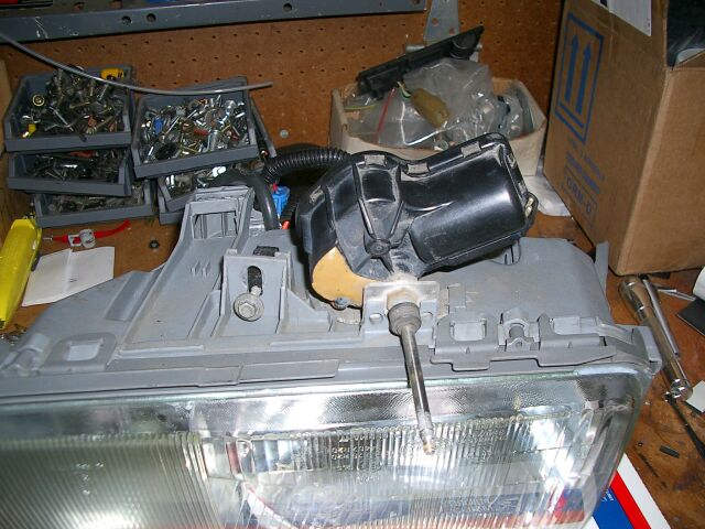
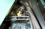
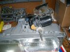
 Here
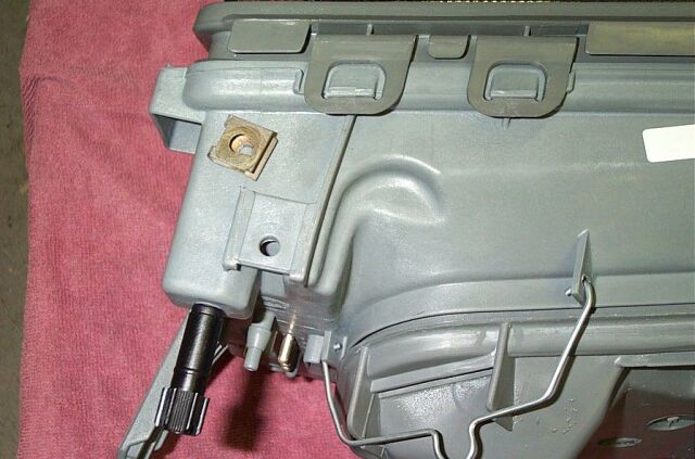
is a rear view of the Euro headlight. You can see the black vacuum
device that allows manual up/down adjustment of the light from inside the
car (on euro cars that is). Vacuum lines can be hooked up to this and run
inside your Mercedes to an adjustment knob that is installed right by your
headlight switch. At some future time I might actually do this but for
now I can live with manually adjusting the lights.
Here
is a rear view of the Euro headlight. You can see the black vacuum
device that allows manual up/down adjustment of the light from inside the
car (on euro cars that is). Vacuum lines can be hooked up to this and run
inside your Mercedes to an adjustment knob that is installed right by your
headlight switch. At some future time I might actually do this but for
now I can live with manually adjusting the lights.
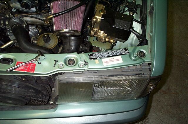
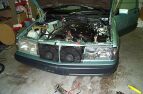
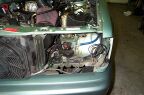
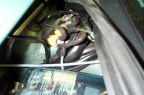
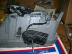
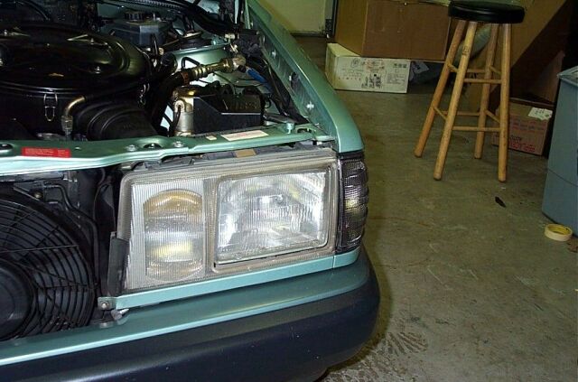
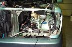 Here
is the 190 with the stock headlight removed. To remove the light, you
must first remove the side marker. The side marker is removed by
unscrewing a small wheel screw located on the inside of the engine
compartment. The side marker will just slide out after removal of the
wheel screw. To remove the headlight, there are two screws on the top
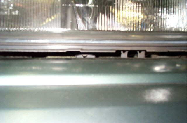
and one screw that is on the bottom. The bottom screw is accessed by
you removing the rubber trim piece at the bottom of the light and then using
a long Philips screwdriver you can get to the screw which is accessed
through the small opening where the rubber trim is.
Here
is the 190 with the stock headlight removed. To remove the light, you
must first remove the side marker. The side marker is removed by
unscrewing a small wheel screw located on the inside of the engine
compartment. The side marker will just slide out after removal of the
wheel screw. To remove the headlight, there are two screws on the top
and one screw that is on the bottom. The bottom screw is accessed by
you removing the rubber trim piece at the bottom of the light and then using
a long Philips screwdriver you can get to the screw which is accessed
through the small opening where the rubber trim is.
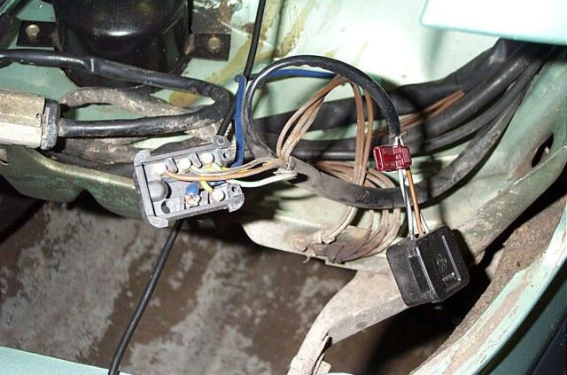
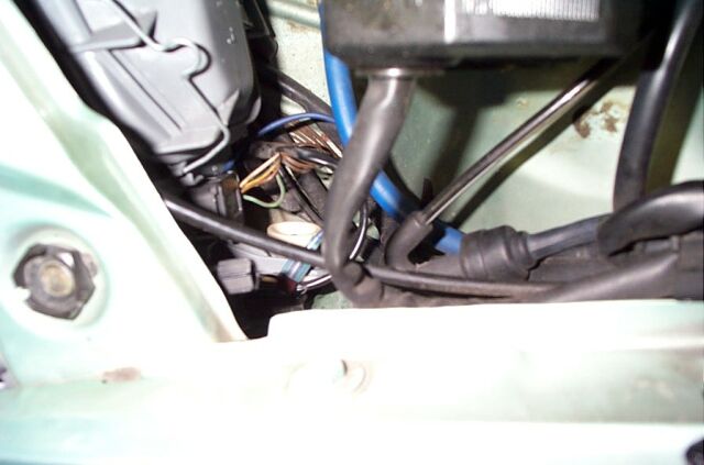
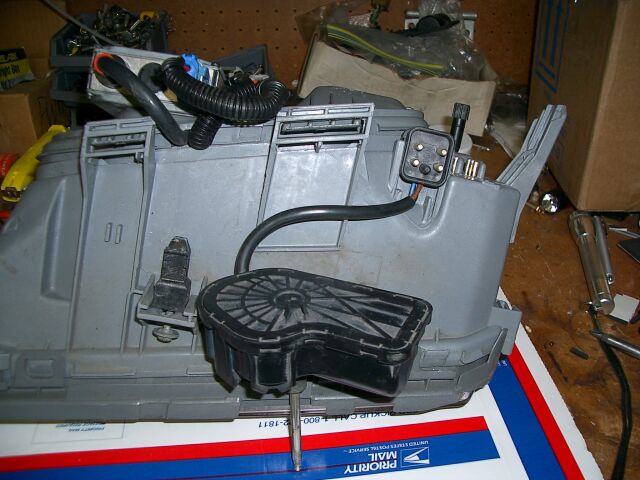
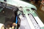
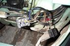 This
picture shows the new euro headlight plug and the correct spots to install
your factory wires. I used a Fluke meter to determine which wire
controlled which function and then traced the wires inside the euro
headlight to find out which ones when for the fogs, high beams etc.
Would of been easier if a wiring schematic was included, oh well. If
you notice the blue wire, that is for the City light. I connected the
blue wire to the side market illumination wire, that way when just the side
markers are turned on the city lights turn on also. For background, in
Europe, the side markets are not blinkers, they use single filament bulbs
just for running lights, their blinkers are the city lights. You can
go this route if you want or you can do what I did. Instead of using
the single filament connectors/bulbs included with the gray side markers, I
used my existing dual filament connector/bulb. I then just added
super-white city lights and wired those to my side markers.
This
picture shows the new euro headlight plug and the correct spots to install
your factory wires. I used a Fluke meter to determine which wire
controlled which function and then traced the wires inside the euro
headlight to find out which ones when for the fogs, high beams etc.
Would of been easier if a wiring schematic was included, oh well. If
you notice the blue wire, that is for the City light. I connected the
blue wire to the side market illumination wire, that way when just the side
markers are turned on the city lights turn on also. For background, in
Europe, the side markets are not blinkers, they use single filament bulbs
just for running lights, their blinkers are the city lights. You can
go this route if you want or you can do what I did. Instead of using
the single filament connectors/bulbs included with the gray side markers, I
used my existing dual filament connector/bulb. I then just added
super-white city lights and wired those to my side markers.
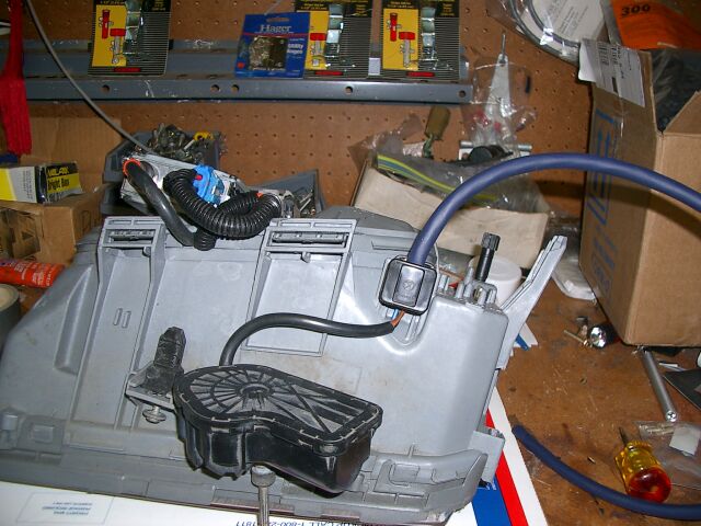
 Here
is a picture of the plug assembled and the blue wire (for the City lights)
connected and in place. One thing I should mention, please use my
information as a guide, but use a multi-meter to make sure that you have the
correct wires in the correct places. I have seen differences in the
colors of the wires that Mercedes uses in the same model from one year to
the next.
Here
is a picture of the plug assembled and the blue wire (for the City lights)
connected and in place. One thing I should mention, please use my
information as a guide, but use a multi-meter to make sure that you have the
correct wires in the correct places. I have seen differences in the
colors of the wires that Mercedes uses in the same model from one year to
the next.

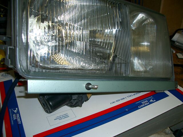
This
is the new Euro headlight with the rubber trim piece installed.
Note: you can really only install the rubber piece after the
headlight is installed, since you have to get that bottom screw in first.
 You
need to remove these clips from your old headlights and use them on your
new Euro's. These clips go on the top
You
need to remove these clips from your old headlights and use them on your
new Euro's. These clips go on the top
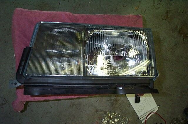
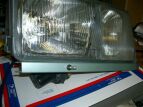
 On
the left is the old headlight (yech!) and on the right is the new.
The Euro headlights have much better optics and glass lenses. The
beam pattern is much better and the existing housing/plugs allow you to
use higher wattage bulbs. The Euro headlights use H4 bulbs for your
low/high beams and H3 for the fogs (same as the stock headlights). I
am running 85/85 watt Piaa Super White H4 bulbs, Nokia 75 watt H3 fogs,
Piaa Super White side marker bulbs and Super White City light bulbs.
Be careful about using colored City light bulbs, in many city's, any
colors other than white or yellow on the front of a car is illegal, so
check your local laws.
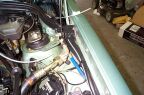
On
the left is the old headlight (yech!) and on the right is the new.
The Euro headlights have much better optics and glass lenses. The
beam pattern is much better and the existing housing/plugs allow you to
use higher wattage bulbs. The Euro headlights use H4 bulbs for your
low/high beams and H3 for the fogs (same as the stock headlights). I
am running 85/85 watt Piaa Super White H4 bulbs, Nokia 75 watt H3 fogs,
Piaa Super White side marker bulbs and Super White City light bulbs.
Be careful about using colored City light bulbs, in many city's, any
colors other than white or yellow on the front of a car is illegal, so
check your local laws.
HID UPGRADE
I have always put off installing HID's in any of my cars because of the
cost, but I finally found a source in Germany, so I arranged to have a set
of Hella ballasts and Philips D2R burners shipped over to me for testing.
These components are OEM for BMW and several other German auto's.
The HID's arrived without instructions or wire harnesses, no problem since
I would be custom making a wire harness and adding relays to power the
HID's.
I did some initial measurements and the Hella ballasts
would not fit under the headlights, so I mounted them on the rear of the
headlights. On other models it may be possible to mount your
ballasts under the lights.
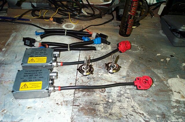
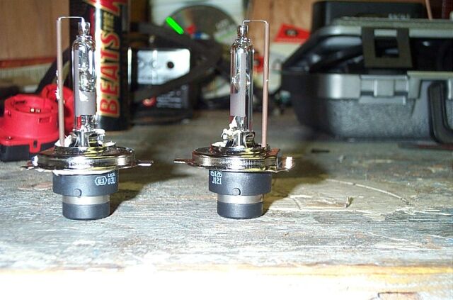
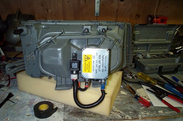
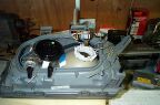
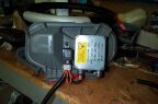
 Here is the
complete kit and the wire harness I put together, I made the harnesses
before I had this kit, so they are way too long, but I will cut them down.
You can also see the Philips D2R burners and I have epoxied H4 metal
mounting rings onto them. You can pull your H4 metal mounting rings
off of your old H4 bulbs.
Here is the
complete kit and the wire harness I put together, I made the harnesses
before I had this kit, so they are way too long, but I will cut them down.
You can also see the Philips D2R burners and I have epoxied H4 metal
mounting rings onto them. You can pull your H4 metal mounting rings
off of your old H4 bulbs.
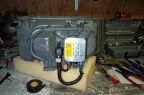
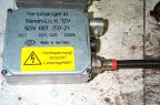 A closer look at
the Hella ballast. Nothing too fancy here, but they are OEM, not a
unit designed for retail sale.
A closer look at
the Hella ballast. Nothing too fancy here, but they are OEM, not a
unit designed for retail sale.
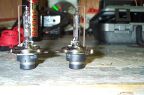 Another close
up shot of the Philips D2R burners with the H4 mounting rings in place.
Another close
up shot of the Philips D2R burners with the H4 mounting rings in place.
 These removal steps
are going to be somewhat redundant, since I pretty much covered all of
this when I initially installed the Euro spec light assemblies, but I will
go over it once again. To remove the light housings, you need to
first remove these two top bolts, they are 8 mm
These removal steps
are going to be somewhat redundant, since I pretty much covered all of
this when I initially installed the Euro spec light assemblies, but I will
go over it once again. To remove the light housings, you need to
first remove these two top bolts, they are 8 mm
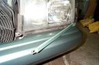
Nest you need to remove the bottom trim piece, it also
is held on with a 8 mm bolt.
Now the rubber weather trim needs to be removed since
there is one more 8 mm bolt to get at.
You can see the 8 mm bolt between the bumper and the
headlight. I would suggest you unscrew it till its almost all the
way out, but not all the way, its a pain if you drop it!
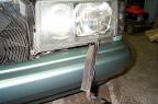
 The last item to
remove is the side marker. On my 201, there is a small white round
nut that needs to be removed before the side marker will come off, you can
see it in this picture.
The last item to
remove is the side marker. On my 201, there is a small white round
nut that needs to be removed before the side marker will come off, you can
see it in this picture.
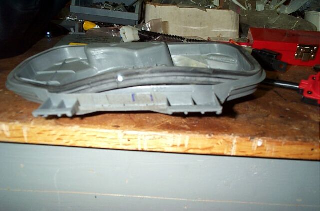
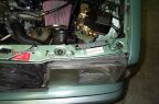
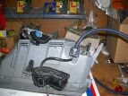
 Here we have the
headlight and the side market removed. Make sure that all the wire
harnesses are out of the way, its easy to get one pinched if your not
carefull.
Here we have the
headlight and the side market removed. Make sure that all the wire
harnesses are out of the way, its easy to get one pinched if your not
carefull.
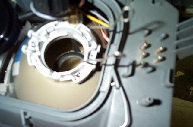
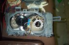
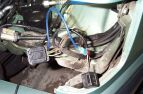
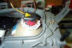
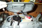
 This is the
headlight with the rear cover removed. I elected to remove the brown
(ground) and the yellow wire (low beam) from the existing socket and use
these as they were to connect to the HID's, the harness and other wires
were tucked out of the way.
This is the
headlight with the rear cover removed. I elected to remove the brown
(ground) and the yellow wire (low beam) from the existing socket and use
these as they were to connect to the HID's, the harness and other wires
were tucked out of the way.

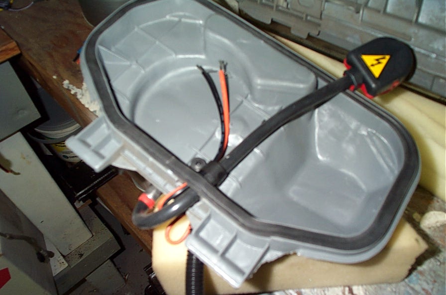
You can see inside
the lens and you will notice that there is a light reflector but it has no
shield mounted in it. The Euro spec headlight assemblies for the
124's do have the shield, so I might play around with adding a shield to
see how the light pattern changes.
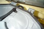
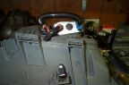
 This is just a test
fitting of the HID burner and the socket. This socket is quite big
and it hits the rear cover of the headlight, but the cover will still go
on. A bit of trimming may need to be done.
This is just a test
fitting of the HID burner and the socket. This socket is quite big
and it hits the rear cover of the headlight, but the cover will still go
on. A bit of trimming may need to be done.
 I decided to bring
the wires from the relay and ballast into the headlight assembly via the
bottom of the rear cover, you can see that it is marked for notching.
This would help in keep out any water that may get into the engine
compartment.
I decided to bring
the wires from the relay and ballast into the headlight assembly via the
bottom of the rear cover, you can see that it is marked for notching.
This would help in keep out any water that may get into the engine
compartment.
 I notched the cover
using a Dremel with a cutting bit. You can see that I also cut a
notch in the rubber seal, just enough to allow the ballast harness to
enter.
I notched the cover
using a Dremel with a cutting bit. You can see that I also cut a
notch in the rubber seal, just enough to allow the ballast harness to
enter.
To mount the Hella
ballast to the rear cover, I used 3M two sided tape, the good stuff
designed for body side molding, very strong. Remember to clean the
rear of the ballast and the rear cover with alcohol so the tape will have
a clean surface to adhere to.
 After the ballast
was secure, I routed the wires through the notch in the cover. I
used a wire clamp to hold the wires in place.
After the ballast
was secure, I routed the wires through the notch in the cover. I
used a wire clamp to hold the wires in place.

 This
is a better picture of the ballast wires going through the notch and the
rubber seal put back in place.
This
is a better picture of the ballast wires going through the notch and the
rubber seal put back in place.
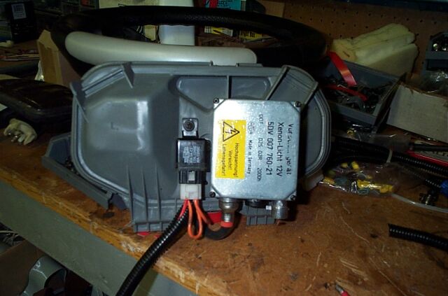
 Here is the rear
cover with the ballast installed and the relay next to it. I found
out later that I needed to move the ballast about .5" to the right (if
your looking at this picture) I had clearance problems with the AC filter
which is right behind the headlight. With the ballast and relay on
the back of the cover, space is very tight and removal of the cover is not
going to be easy. This only happens on the drivers side, on the
passenger side, there is much more clearance, this step by step
instruction covers the drivers side installation, I did not document the
passenger side.
Here is the rear
cover with the ballast installed and the relay next to it. I found
out later that I needed to move the ballast about .5" to the right (if
your looking at this picture) I had clearance problems with the AC filter
which is right behind the headlight. With the ballast and relay on
the back of the cover, space is very tight and removal of the cover is not
going to be easy. This only happens on the drivers side, on the
passenger side, there is much more clearance, this step by step
instruction covers the drivers side installation, I did not document the
passenger side.
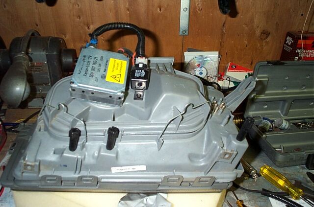
 This picture shows
everything connected and were ready to close the rear cover.
This picture shows
everything connected and were ready to close the rear cover.
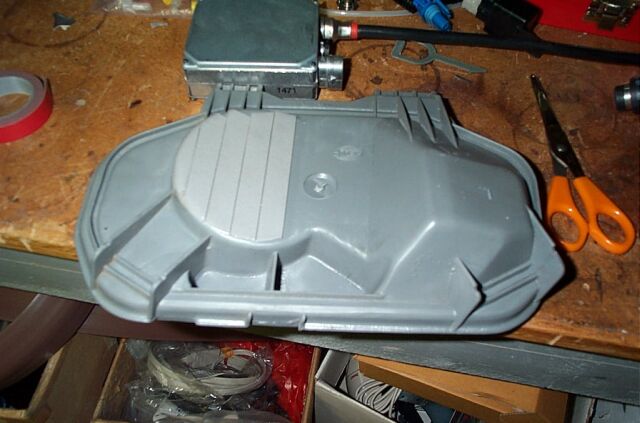
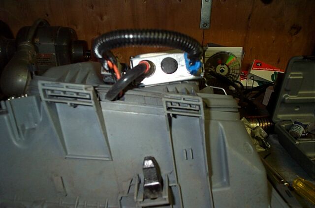
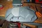
 Another picture of
the finished light assembly with the rear cover in place.
Another picture of
the finished light assembly with the rear cover in place.
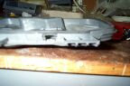
And another
picture detailing the bottom the headlight assembly
 This is a picture
of the rear, you can see all the relay wire was covered in split loom
tubing.
This is a picture
of the rear, you can see all the relay wire was covered in split loom
tubing.
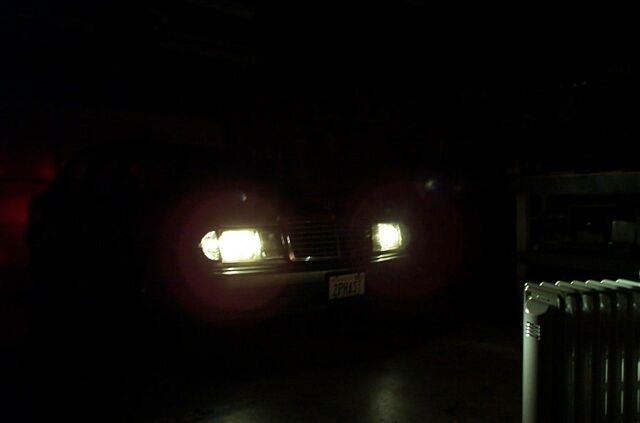
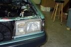
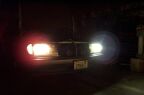
 This picture
shows the euro headlights with Piaa 80/80watt SuperWhite bulbs on both
sides (before the HID upgrade)
This picture
shows the euro headlights with Piaa 80/80watt SuperWhite bulbs on both
sides (before the HID upgrade)
 Here you can see
the Piaa on the left and the HID on the right, what a difference in color
and brightness!
Here you can see
the Piaa on the left and the HID on the right, what a difference in color
and brightness!
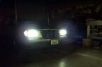
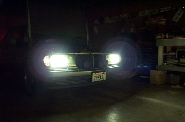
Finally, a
picture of both HID's! I had to spend a bit of time tweaking the
alignment of these HID's, they project light so far down the street and
way off to both sides of the vehicle. I am very impressed so far.
As for color, these appear to be in the 4100K color range, very white to a
light blue in color. As I mentioned, the euro headlight assemblies
have the light reflector directly in front of the bulb, but there is no
cap on the reflector, so I may try to fabricate something to see what if
any difference in light output or the projection pattern.
EURO HEADLIGHT ADJUSTER
In Europe, Mercedes Benz models come with a nice feature that allows
you to adjust the level of your headlights from inside the car. For
US consumption, we don't get the Euro headlights (with internal vacuum
adjuster) or the inside adjustment switch. Previously in this
section you read about the install of Hella Euro headlights, these lights
have the internal vacuum adjustment capability, but I still needed a
switch, fortunately I bought some parts from a person in Germany and he
sold me the Euro headlight adjustment switch and panel for $1 Euro dollar.
Now I am ready to make the headlights adjustable!
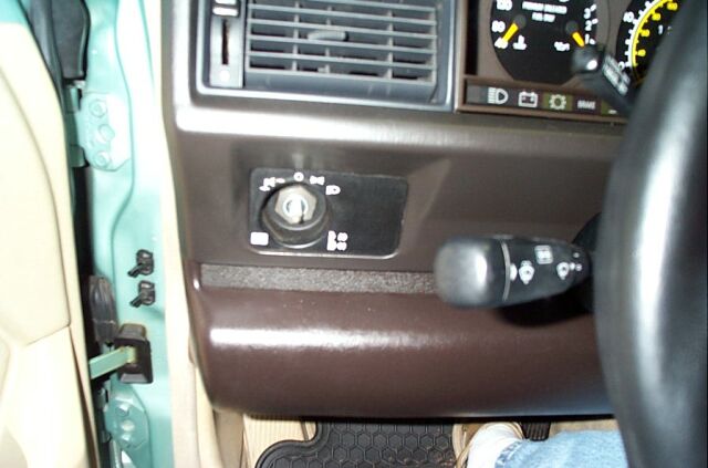
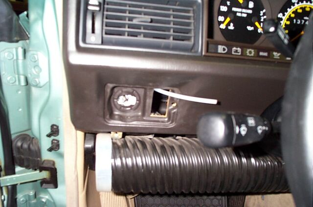
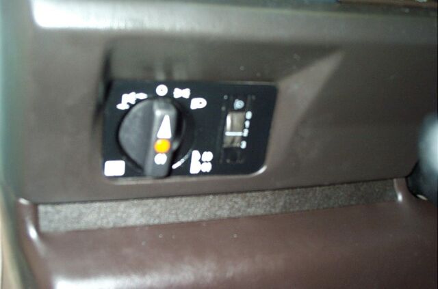
This is the US spec headlight control and panel. To remove, you
pull off the headlight switch
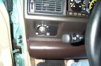 and use
a 24mm socket to remove the nut. On the right side of the switch
panel is a post that had some sort of speed nut on the end of it, not sure
how you are "officially" supposed to remove it, but in the process of
trying to figure that out, it broke. Its possible that you would
have to remove the instrument cluster to get access, so keep that in mind
if you attempt this upgrade.
and use
a 24mm socket to remove the nut. On the right side of the switch
panel is a post that had some sort of speed nut on the end of it, not sure
how you are "officially" supposed to remove it, but in the process of
trying to figure that out, it broke. Its possible that you would
have to remove the instrument cluster to get access, so keep that in mind
if you attempt this upgrade.
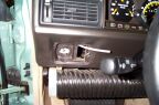
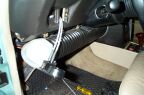
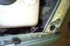
Here
is a picture of the dash with the switch cover removed, you can see that
there is already an opening for the headlight adjustment switch. You
can also see that I removed the knee bolster cover to gain access to under
the dash. Your going to need to do this (if you don't pull your
instrument cluster) so you can feed the vacuum tube from the engine
compartment to the switch opening.
Here you can see the large rubber grommet that I fed the vacuum line
through. You can use needle nose pliers to pull off the rubber
ends to make a hole to feed the tube through. The
 tube I
used is standard MB vacuum tube used throughout the engine bay, its about
1/8" in diameter and is about $1.50 per 3 meters from the dealer.
Also, to do this install, figure about 15 feet of tube, two rubber vacuum
"T" couplers, two straight rubber couplers and two right angle rubber
couplers. Depending upon where you draw a vacuum source from, you
may also need a check valve, this keeps pressure in the line when the
vehicle is turned off, the black end of the valve goes towards the vacuum
source. All these couplers and check valve are available at your
local auto parts store which is less expensive then picking them up at the
dealer.
tube I
used is standard MB vacuum tube used throughout the engine bay, its about
1/8" in diameter and is about $1.50 per 3 meters from the dealer.
Also, to do this install, figure about 15 feet of tube, two rubber vacuum
"T" couplers, two straight rubber couplers and two right angle rubber
couplers. Depending upon where you draw a vacuum source from, you
may also need a check valve, this keeps pressure in the line when the
vehicle is turned off, the black end of the valve goes towards the vacuum
source. All these couplers and check valve are available at your
local auto parts store which is less expensive then picking them up at the
dealer.
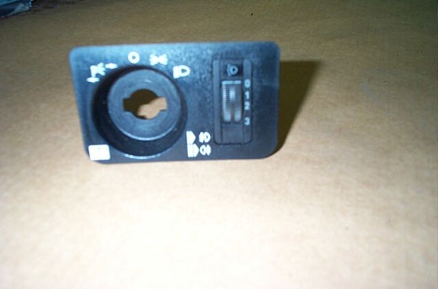
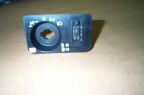 This is
the Euro light switch cover and headlight adjustment switch as it arrived
from Germany. Although a used item, it is in excellent condition
(genuine Bosch item)
This is
the Euro light switch cover and headlight adjustment switch as it arrived
from Germany. Although a used item, it is in excellent condition
(genuine Bosch item)
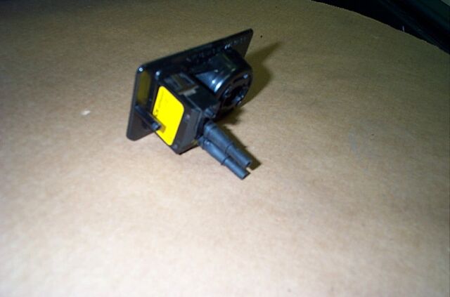
 This is the
back of the euro headlight adjustment switch, you can see that I installed
the two straight rubber couplers..
This is the
back of the euro headlight adjustment switch, you can see that I installed
the two straight rubber couplers..
Another picture of the vacuum line pulled and connected to the headlight
adjustment switch.
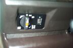
Once the lines are connected, you can install the headlight switch cover
and adjustment switch. This particular switch has illumination
capability, but I had no easy access to any light source to hook up to it,
so I will leave that as a project for a later time.
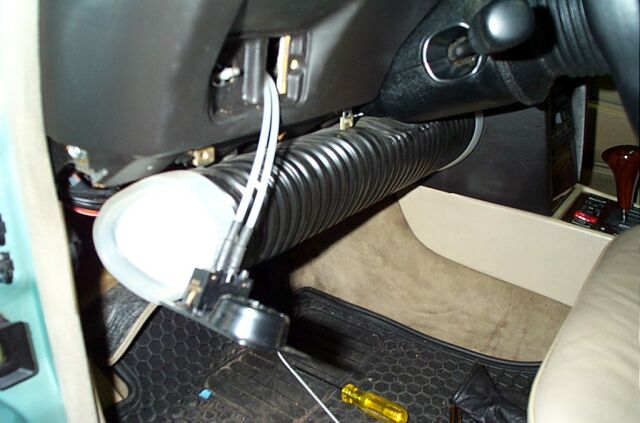
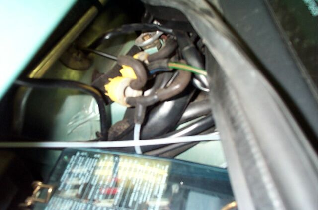
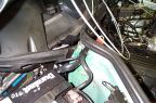
 In this
picture you can see the two vacuum lines and if you notice, there is a
yellow blow back valve that had a rubber right angle coupler removed, this
is where I chose to get my vacuum source from. Some people have used
the economy gauge on the back of the instrument cluster, but my model does
not have that feature.
In this
picture you can see the two vacuum lines and if you notice, there is a
yellow blow back valve that had a rubber right angle coupler removed, this
is where I chose to get my vacuum source from. Some people have used
the economy gauge on the back of the instrument cluster, but my model does
not have that feature.
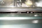
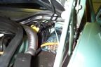
 Here you
can see how I used a rubber "T" coupler to tap into this existing vacuum
source. A important note to remember, The vacuum source goes into
the top connector on the switch (# 1) and the line to the headlights on
the bottom connector of the switch (# 2)
Here you
can see how I used a rubber "T" coupler to tap into this existing vacuum
source. A important note to remember, The vacuum source goes into
the top connector on the switch (# 1) and the line to the headlights on
the bottom connector of the switch (# 2)
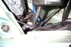
 If you
look closely in this picture you will see the right angle rubber coupler
attached to the headlight and the clear vacuum tube coming up and routed
with the factory wire harness.
If you
look closely in this picture you will see the right angle rubber coupler
attached to the headlight and the clear vacuum tube coming up and routed
with the factory wire harness.
Another picture of the drivers side vacuum tubing routed with the factory
wire harness and routed through the bulk head via a blank spot in a rubber
grommet.
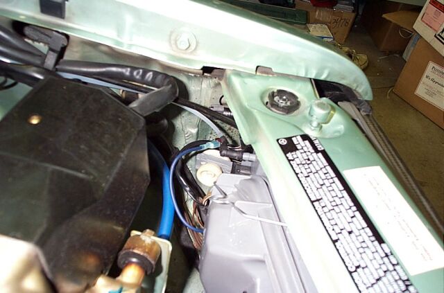
 This
picture is of the passenger side and shows the rubber right angle coupler
and the vacuum tube entering the factory wire harness.
This
picture is of the passenger side and shows the rubber right angle coupler
and the vacuum tube entering the factory wire harness.
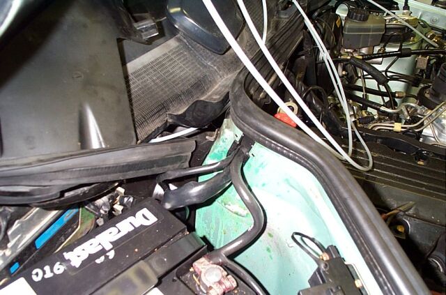
 On the passenger side, the vacuum tube was routed up to another rubber
grommet in the bulk head. After going through the rubber grommet, I
removed the black plastic cover behind the
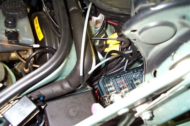
battery. The tube was routed behind the ECU and up into a small
opening that leads to the center grill area (grill that covers the wiper
internals) There are two screws to remove to allow semi access to this
compartment, I used that access to get the tube and feed it to the other
side.
On the passenger side, the vacuum tube was routed up to another rubber
grommet in the bulk head. After going through the rubber grommet, I
removed the black plastic cover behind the
battery. The tube was routed behind the ECU and up into a small
opening that leads to the center grill area (grill that covers the wiper
internals) There are two screws to remove to allow semi access to this
compartment, I used that access to get the tube and feed it to the other
side.
 In this
last picture you can see how I used a rubber "T" to connect the two
headlight tubes together, all this tubing was neatly tucked away beside
the fuse block, its pulled out for purposes of this picture. It took
about 1.5" hours to do this install and it works very well. Its a
excellent upgrade for those who have Euro lights.
In this
last picture you can see how I used a rubber "T" to connect the two
headlight tubes together, all this tubing was neatly tucked away beside
the fuse block, its pulled out for purposes of this picture. It took
about 1.5" hours to do this install and it works very well. Its a
excellent upgrade for those who have Euro lights.
8/18/03 Euro Headlight Wipers!
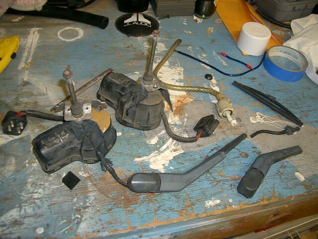
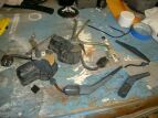 I
sourced these from Germany for around $60. The package included the
motors, wiper arms, wiper blades and a Y splitter for the washer fluid.
Since I am using Euro headlights, I had to use Euro wipers.
I
sourced these from Germany for around $60. The package included the
motors, wiper arms, wiper blades and a Y splitter for the washer fluid.
Since I am using Euro headlights, I had to use Euro wipers.

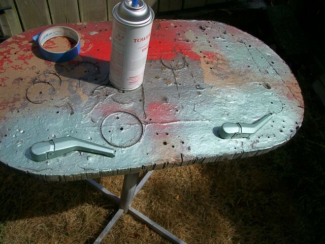
Staying
with my "mono" colored scheme, I painted the wiper arms body color.
Its important that you prep the items correctly for a nice, even finish.
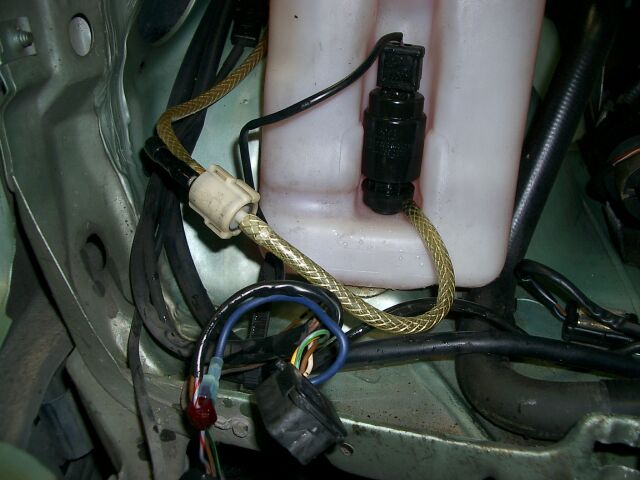
 190's
with headlight wipers normally have a different wiper fluid tank and an
extra pump for the wipers. When I manage to locate one of those I
will get one but for now, I used the Y splitter to tap off of the existing
pump so I can feed tubing to the front headlight wipers.
190's
with headlight wipers normally have a different wiper fluid tank and an
extra pump for the wipers. When I manage to locate one of those I
will get one but for now, I used the Y splitter to tap off of the existing
pump so I can feed tubing to the front headlight wipers.
The
wiper motor mounts to the OEM spot on the Euro lights and secures via a
small screw. This part is pretty simple
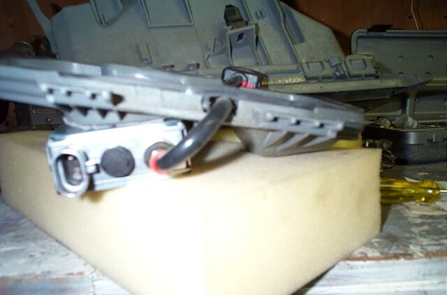
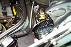
 You
can see here that the plug for the wiper motor has a nice spot it snaps
into.
You
can see here that the plug for the wiper motor has a nice spot it snaps
into.
As
with most Mercedes, if you did not purchase an option from the factory,
Mercedes normally does not include any wiring and/or relays. Thus is
the case with the wipers, no wire harness. I fabricated my own wire
harness using plugs left over from my original headlights. Not quite
as clean as Mercedes but it works.
 I
chose to use my existing headlight trim so holes needed to be drilled for
the wiper motor stalk and for the washer fluid plug. I would suggest
getting new, euro trim pieces with the holes already pre-drilled.
Its hard to get the holes just perfect. I ended up using some rubber
grommets and still had to dremel out the insides to get a good snag free
fit.
I
chose to use my existing headlight trim so holes needed to be drilled for
the wiper motor stalk and for the washer fluid plug. I would suggest
getting new, euro trim pieces with the holes already pre-drilled.
Its hard to get the holes just perfect. I ended up using some rubber
grommets and still had to dremel out the insides to get a good snag free
fit.
The
finished product! Antithetically, I really like the look of the Euro
wipers, especially painted body color.

<Back
 Next on the agenda was to do something
about the terrible lighting that this Mercedes has (hmm, maybe I should say
terrible lighting that all Mercedes have). Of course the logical
course of action was to acquire a set of Euro headlights which I purchased
through www.puma-access.com on a
group purchase for $290. I also picked up a set of gray side markers
which in my opinion are a better match to the euro headlights than the white
side markers. I don't have complete step by step instructions for this
install, but I do have some pictures that can assist you with your own euro
headlight install. This picture here shows the ugly, yellowing factory
headlight that provides little light at night
Next on the agenda was to do something
about the terrible lighting that this Mercedes has (hmm, maybe I should say
terrible lighting that all Mercedes have). Of course the logical
course of action was to acquire a set of Euro headlights which I purchased
through www.puma-access.com on a
group purchase for $290. I also picked up a set of gray side markers
which in my opinion are a better match to the euro headlights than the white
side markers. I don't have complete step by step instructions for this
install, but I do have some pictures that can assist you with your own euro
headlight install. This picture here shows the ugly, yellowing factory
headlight that provides little light at night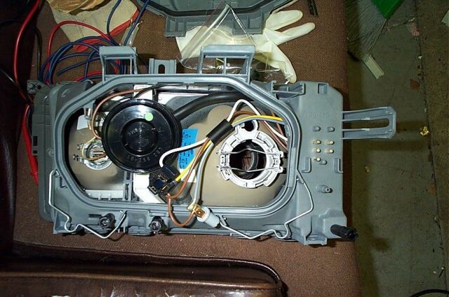 Here
is a rear view of the Euro headlight. You can see the black vacuum
device that allows manual up/down adjustment of the light from inside the
car (on euro cars that is). Vacuum lines can be hooked up to this and run
inside your Mercedes to an adjustment knob that is installed right by your
headlight switch. At some future time I might actually do this but for
now I can live with manually adjusting the lights.
Here
is a rear view of the Euro headlight. You can see the black vacuum
device that allows manual up/down adjustment of the light from inside the
car (on euro cars that is). Vacuum lines can be hooked up to this and run
inside your Mercedes to an adjustment knob that is installed right by your
headlight switch. At some future time I might actually do this but for
now I can live with manually adjusting the lights. Here
is the 190 with the stock headlight removed. To remove the light, you
must first remove the side marker. The side marker is removed by
unscrewing a small wheel screw located on the inside of the engine
compartment. The side marker will just slide out after removal of the
wheel screw. To remove the headlight, there are two screws on the top
and one screw that is on the bottom. The bottom screw is accessed by
you removing the rubber trim piece at the bottom of the light and then using
a long Philips screwdriver you can get to the screw which is accessed
through the small opening where the rubber trim is.
Here
is the 190 with the stock headlight removed. To remove the light, you
must first remove the side marker. The side marker is removed by
unscrewing a small wheel screw located on the inside of the engine
compartment. The side marker will just slide out after removal of the
wheel screw. To remove the headlight, there are two screws on the top
and one screw that is on the bottom. The bottom screw is accessed by
you removing the rubber trim piece at the bottom of the light and then using
a long Philips screwdriver you can get to the screw which is accessed
through the small opening where the rubber trim is.