Stereo and Keyless entry upgrades.
 This
500E arrived with a Pioneer DEH-P9300 in-dash CD. While a nice unit, it
did not play MP3's, only audio CD's. Attached to it was a 12 disk Pioneer
CD changer as well. This was a fairly high end deck a few years back and
the sound quality and feature set was very rich.
This
500E arrived with a Pioneer DEH-P9300 in-dash CD. While a nice unit, it
did not play MP3's, only audio CD's. Attached to it was a 12 disk Pioneer
CD changer as well. This was a fairly high end deck a few years back and
the sound quality and feature set was very rich.
 You
need the Pioneer removal keys to pull the unit from the dash. I took the
liberty to clean up the rats nest left by the person who installed the previous
head unit.
You
need the Pioneer removal keys to pull the unit from the dash. I took the
liberty to clean up the rats nest left by the person who installed the previous
head unit.
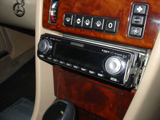
 For
my replacement, I chose to stay with Pioneer, mainly since this particular brand
is one of the few still making Mosfet high power head
units.
The DEH-P8MP Premier has a internal Mosfet 60 internal amp (versus the 50 watt
Mosfet amplifier of the DEH-P9300) although this head unit does not have some of
the sound shaping functionality of the previous deck, the sound quality is very
good. The additional power is put to good use powering the front 4" dash
speakers and the rear 5.25" speakers. The door speakers are powered by a
small ADS amplifier.
For
my replacement, I chose to stay with Pioneer, mainly since this particular brand
is one of the few still making Mosfet high power head
units.
The DEH-P8MP Premier has a internal Mosfet 60 internal amp (versus the 50 watt
Mosfet amplifier of the DEH-P9300) although this head unit does not have some of
the sound shaping functionality of the previous deck, the sound quality is very
good. The additional power is put to good use powering the front 4" dash
speakers and the rear 5.25" speakers. The door speakers are powered by a
small ADS amplifier.
 Next
on the agenda was the addition of some low end. I did experiment a bit
with Bandpass and some sealed box designs, but they consumed to much trunk space
and required additional amplification and space. Although all these
designs provided ample bass, much of which does get into the passenger cabin
very well without the need for rear deck venting. This time around, I
stepped up to the Basslink T. A single 10" sub mounted between two passive
radiators and a internal 250watt amplifier. The length is about 40", which
is ideal for the length of the 500E trunk. This picture shows a test
fitting before I mount it.
Next
on the agenda was the addition of some low end. I did experiment a bit
with Bandpass and some sealed box designs, but they consumed to much trunk space
and required additional amplification and space. Although all these
designs provided ample bass, much of which does get into the passenger cabin
very well without the need for rear deck venting. This time around, I
stepped up to the Basslink T. A single 10" sub mounted between two passive
radiators and a internal 250watt amplifier. The length is about 40", which
is ideal for the length of the 500E trunk. This picture shows a test
fitting before I mount it.

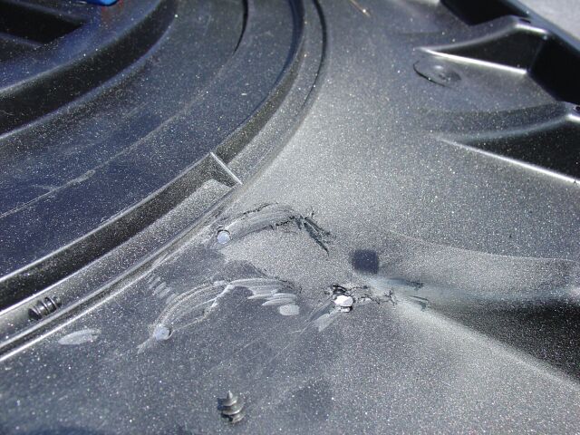
To start, I
needed to remove the trunk carpet, spare wheel and accessories. Mainly, I
wanted to clean this area up and ensure I don't drill into my spare tire!
While the Basslink was in the trunk, I marked the location of the feet so I
could drill the necessary holes for mounting. The passenger side mount sat
on top of the plastic spare wheel cover, which is not a big deal.

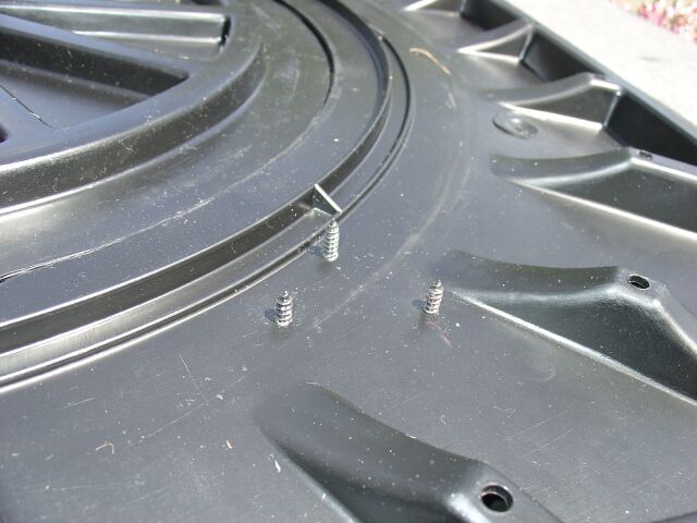
Because the screws for the mounting foot would probably puncture the spare tire,
they were trimmed flush to the bottom of the plastic cover using the trusty
Dremel.
Not I am ready to put everything back into the trunk and continue with the
install. With the passenger side Basslink mount secured to this cover,
access to the spare tire is not possible, but by removing these three screws, I
can lift the cover up enough to slide it out without disturbing the Basslink.
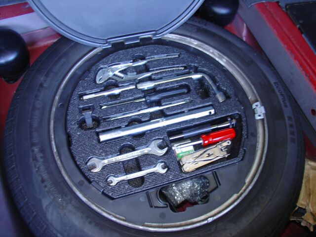 As
seen elsewhere on my site, this is the W140 spare tire tool kit, nicely cleaned
up an with a few of my own additions.
As
seen elsewhere on my site, this is the W140 spare tire tool kit, nicely cleaned
up an with a few of my own additions.
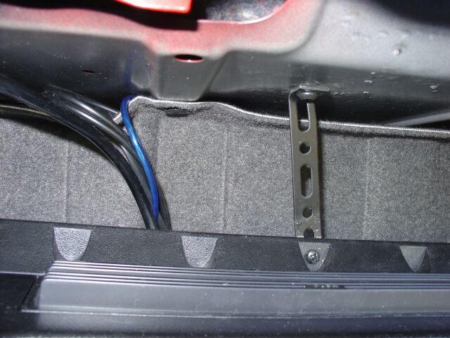
I did not want to rely on just the mounting feet to secure the Basslink in the
trunk. Plus, if I unbolt the passenger side mounting foot (to get at the
spare tire) I wanted to make sure the Basslink did not become unstable. So
I used some back strapping material mounted to the top of the Basslink and
secured to the underside of the rear deck. Normally silver, I painted this
back strapping material flat black to better blend with the interior. You
can also see the signal/power cable that rises up and drops behind the trim
panel.

And the finished product! I sacrificed less than 7" of the trunk depth and
only a minor inconvenience when accessing the spare tire. The power/ground
were routed behind the trim panels over to the battery where they were wired
directly to the battery. I used a JL Audio install kit which includes 8
gage power/ground and a fuse at the +12 terminal of the battery. As
always, Infinity makes a quality product that is clean and tight sounding.
The Basslink T includes a remote volume control that connects to the internal
amplifier via a standard RJ-11 phone cable. I routed this cable along the
drivers side of the vehicle up into the light switch area of the dash.

You can see the cable in this picture as it runs up between the kick panel and
the body of the car. From there, its easy to snake it into the dash area.
This is the Basslink volume control in its self contained box. Of
course, mounting this under the dash was not going to provide the best
appearance, so I elected to take the volume control apart and flush it into the
headlight trim panel.
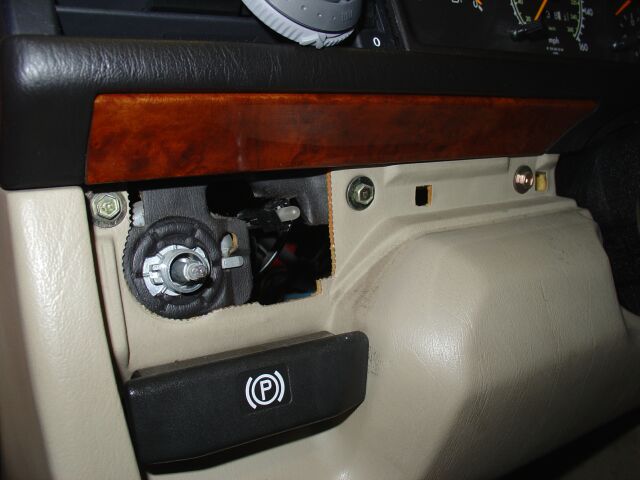
 This
is the volume control dissembled. I mounted it where the euro headlight
adjustment would normally be.
This
is the volume control dissembled. I mounted it where the euro headlight
adjustment would normally be.

Using the trusty Dremel again, a hole large enough for the volume control shaft
was drilled and the nut and lock washer was installed prior to installing the
volume knob.
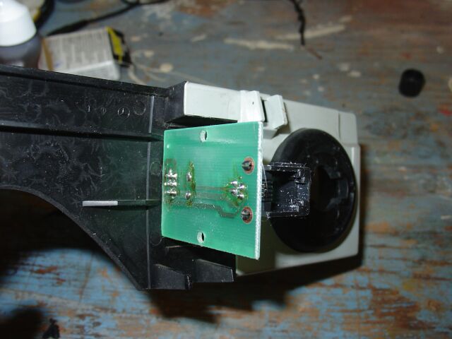
This is the rear of the volume control after mounting. To provide a
additional level of safety, all metal ckt contact points were insulated with
electrical tape before being mounted.

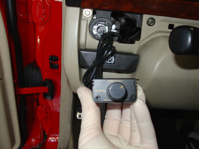
The finished product. A nice OEM look which provides easy access while
driving the vehicle.
Keyless Entry install
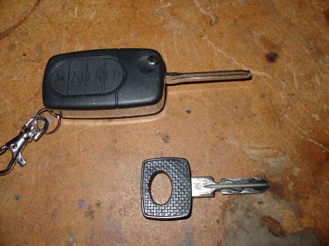
 This
keyless entry system is also a full featured alarm that comes with flip-key
remotes very similar to the late 90's Mercedes remotes. Of course, this
alarm did not have key blanks for Mercedes, but then again, you wouldn't want to
use the supplied ones anyway, since they are brass. These are readily
available from Ebay for around $40 or so.
This
keyless entry system is also a full featured alarm that comes with flip-key
remotes very similar to the late 90's Mercedes remotes. Of course, this
alarm did not have key blanks for Mercedes, but then again, you wouldn't want to
use the supplied ones anyway, since they are brass. These are readily
available from Ebay for around $40 or so.

Some more of the alarm accessories. The instruction manual was a joke
though, poorly translated and barely understandable, lucky for me I have
installed hundreds of security systems.
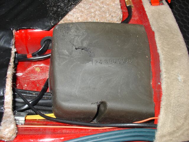
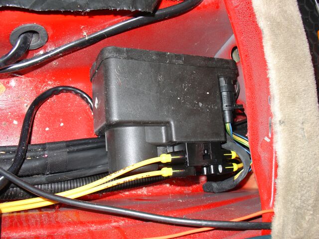
Under the passenger side of the rear seat lies the vacuum motor for the door
locks. This is where the majority of the work is going to take place.
Although not 100% accurate and written for a specific model of keyless entry, I
referenced this instructions,
http://www.mercedesshop.com/Wikka/W124Keyless between these instructions and
mine, I believe just about anyone should be able to complete this installation.
Instructions for removing the covers and vacuum lines are covered in the other
instructions so I won't duplicate them here.
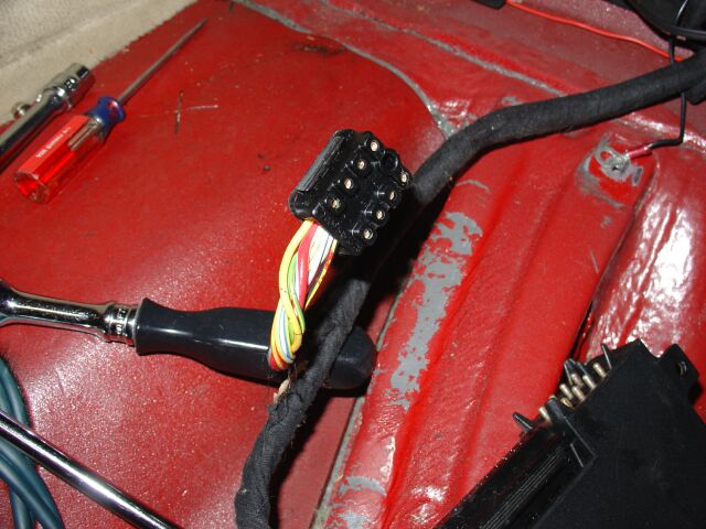
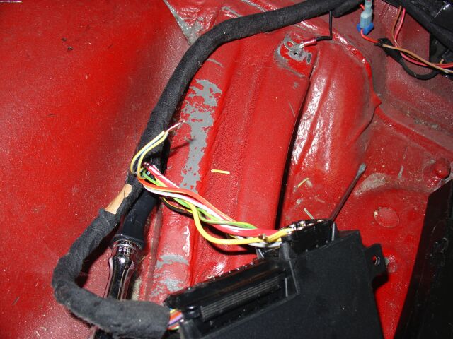
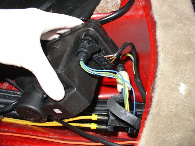 Here
are the two plugs we need to access. The three wire plug contains the
ground, +12 and switched +12. I chose to use the green wire from the round
plug, the green is from the passenger door, blue the drivers and yellow the
trunk. Any of these three will work. Later model W124's have six
wires here, two of each color, but only one of each color is the correct wire to
use. Consult the other install guide for directions on locating that wire.
Here
are the two plugs we need to access. The three wire plug contains the
ground, +12 and switched +12. I chose to use the green wire from the round
plug, the green is from the passenger door, blue the drivers and yellow the
trunk. Any of these three will work. Later model W124's have six
wires here, two of each color, but only one of each color is the correct wire to
use. Consult the other install guide for directions on locating that wire.
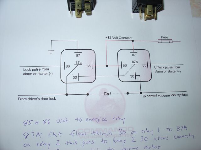
The alarm I chose does have on-board relays and includes several different ways
to wire them for different types of door locks, but they don't include
the single wire +12/-12 lock/unlock method that Mercedes employs. So I set
the alarm to just emit a -12 lock and a -12 on unlock, then I used two outboard
SPDT relays wired up as per this diagram. At rest, the door ckt operates
normally, when energized, the ckt is broken and either a +12 or -12 is sent to
the vacuum motor. Of course, what the other site does not tell you is that
there is no way to initiate a arm/disarm of your factory alarm from this
location.
If you need this system to arm/disarm your factory security system, you need to
run your -12 trigger wires from your alarm up to the factory alarm brain
location. Now keep in mind that your wires/colors may vary, just use my
information as a guide and remember to always test your wires to ensure they are
the correct ones. Connector 2 (small one) on the alarm brain is the where
we find the wires. If you unplug it like this.
Your going to need the wire located in Pin number 6 (yellow w/blue stripe) to
arm the alarm. You need Pin 7 (green with yellow stripe) to disarm the
alarm. At rest these wires are +12, to arm, pin 6 goes to -12. To
disarm, pin 7 goes to -12.
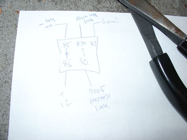
This is the relay diagram I came up with for the arm/disarm of the alarm.
You need one relay for arm and one for disarm. NOTE, I realized a mistake
AFTER I took the picture, 87a should go to the door lock harness and 30 should
be the alarm brain. Please remember this if you use this relay diagram.
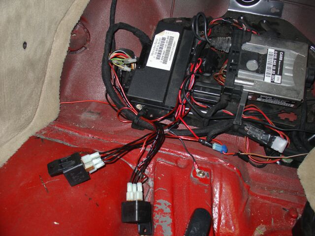
Here are my arm/disarm wires spliced into my alarm brain. When finished,
everything tucks away nicely.
So, getting back to the flip key remote. The next step was to cut down my
OE steel key so it would fit the flip key remote. This process requires a
Dremel, some cutting wheels, grinding wheels and some small files to get the job
done.

You need the original flip key blank to use as a guide, so you need to remove
two small screws that hold it into the remote, don't loose the
screws when you take them out, they are very small.
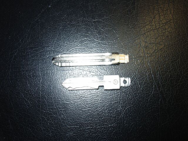
Basically, you need to make your original key look like the key you removed from
the remote. Notice the tab end of the key, you want to duplicate this on
your key using the tools mentioned above. You need to be very precise,
otherwise it will not fit/work correctly.

Keep working your key until it fits perfect and you can put the retainer screws
back in. Also test the opening/closing of the key, it needs to be centered
correctly.
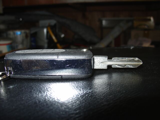
The results were very well worth the effort, now arming/disarming of the alarm
locks the doors and arms the factory security system as well.
Here are additional instructions in Japanese to do the flip key modification
http://to-fit.co.jp/newkeyless/hand.htm
<Back
Information/pictures on this site are the property of Rik Johnson and are not
to be used without written permission.