Performance Upgrades
Engine ECU Chip 4-15-06
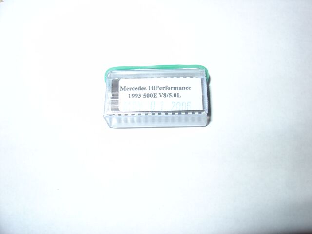 Although
chipping the 500E does not net alot of power, if you can chip it for little
money, its worth it to eliminate the 155 top speed and cold start up-shift delay.
Chances are this chip only nets about 5-7 hp, but for $69, I believe its was a
good investment. This came from EBay and I am sure the seller is coping
another companies product, but it is a exact fit and works as described.
Although
chipping the 500E does not net alot of power, if you can chip it for little
money, its worth it to eliminate the 155 top speed and cold start up-shift delay.
Chances are this chip only nets about 5-7 hp, but for $69, I believe its was a
good investment. This came from EBay and I am sure the seller is coping
another companies product, but it is a exact fit and works as described.
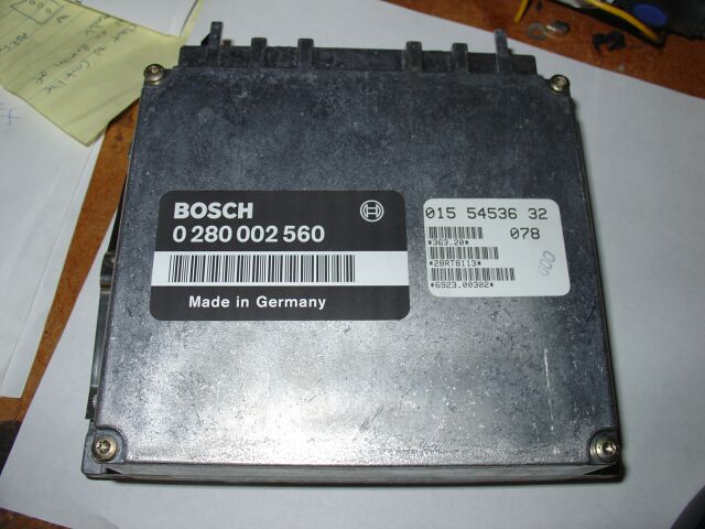 So
we start by pulling out the LH Computer. See my instructions under the ASR
defeat section for a how-to on this.
So
we start by pulling out the LH Computer. See my instructions under the ASR
defeat section for a how-to on this.
 The
chip ships with instructions on how to dissemble your computer, you will need
some torx bits and a clean area to take your computer apart.
The
chip ships with instructions on how to dissemble your computer, you will need
some torx bits and a clean area to take your computer apart.
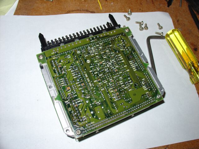 There
are torx screws on both sides of the computer circuit boards. When you
remove them, put them in neat piles so you can remember which side they came
from.
There
are torx screws on both sides of the computer circuit boards. When you
remove them, put them in neat piles so you can remember which side they came
from.
 When
all the torx screws are removed, you can remove the top circuit board and flip
it over, being careful of the ribbon cable. The computer chip is under the
white plastic cover. A small flat blade screw driver will allow you to pop
this cover off.
When
all the torx screws are removed, you can remove the top circuit board and flip
it over, being careful of the ribbon cable. The computer chip is under the
white plastic cover. A small flat blade screw driver will allow you to pop
this cover off.
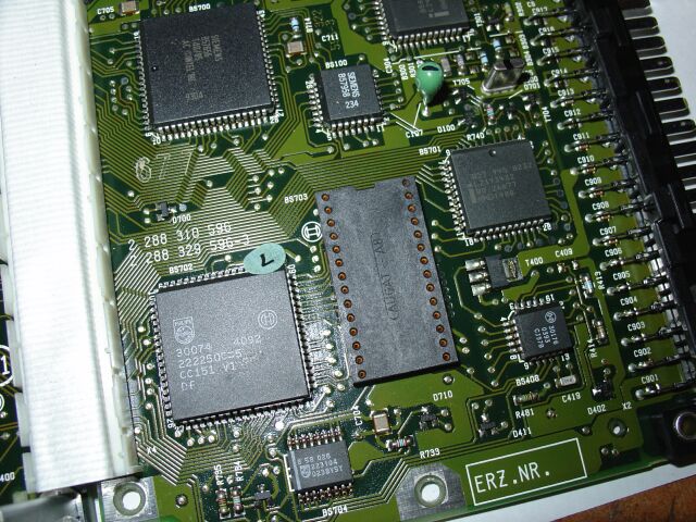
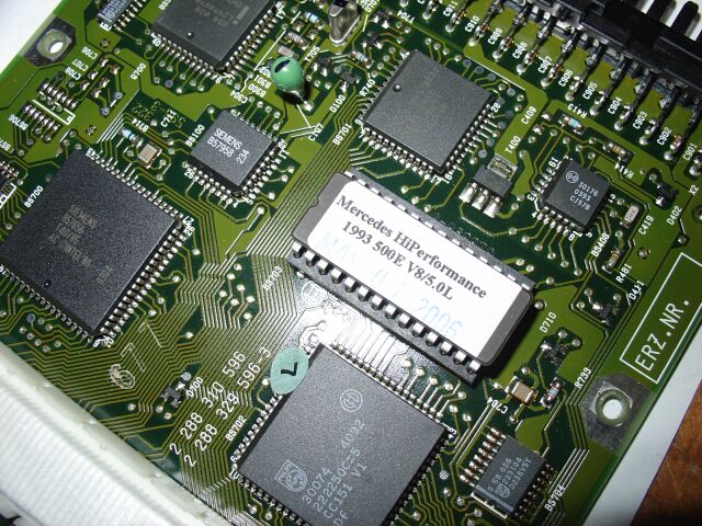
 With
the white chip cover off, you can see the label of the chip. The chip is
notched at one end, be sure to remember this when it is time to install the new
chip.
With
the white chip cover off, you can see the label of the chip. The chip is
notched at one end, be sure to remember this when it is time to install the new
chip.
 To
remove the old chip, I used a small flat blade screw driver under each end of
the chip, prying up gently, a little at a time. Be careful, you don't want
to bend any of the pins in the process.
To
remove the old chip, I used a small flat blade screw driver under each end of
the chip, prying up gently, a little at a time. Be careful, you don't want
to bend any of the pins in the process.
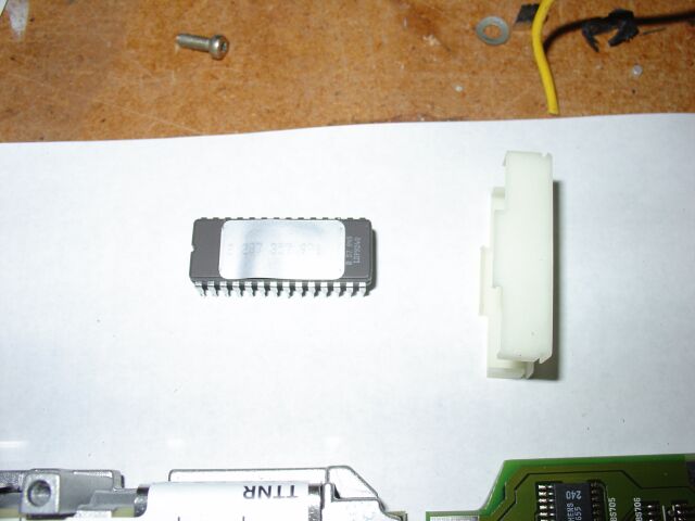 The
new chip arrives in a plastic carrier and it also comes with more detailed
instructions for install.
The
new chip arrives in a plastic carrier and it also comes with more detailed
instructions for install.
 When
it is time to install your new chip, you should try not to touch the pins or
bend them in the process. Sometimes though, the chips need to be slightly
bent inward before it will seat into the socket. Be careful not to bend
any of the pins, make sure the chip is aligned correctly (see the notches on the
chip and the socket) and lastly, make sure it is fully seated before you put
everything back together.
When
it is time to install your new chip, you should try not to touch the pins or
bend them in the process. Sometimes though, the chips need to be slightly
bent inward before it will seat into the socket. Be careful not to bend
any of the pins, make sure the chip is aligned correctly (see the notches on the
chip and the socket) and lastly, make sure it is fully seated before you put
everything back together.
6-17-09 - 1992 LH Computer Install
 After
getting the 500e on the dyno, I noticed the stock 93 ecu runs lean, even
with the performance chip installed. This lean condition caused a
serious power drop. The 1992 500e had 7 more hp, due to WOT enrichment
(322 hp vs. 315 hp for 93/94). A common mod is to install the 1992 ECU
into the later model cars, not only does this net 7 more hp, but it richens
the A/F mixture.
After
getting the 500e on the dyno, I noticed the stock 93 ecu runs lean, even
with the performance chip installed. This lean condition caused a
serious power drop. The 1992 500e had 7 more hp, due to WOT enrichment
(322 hp vs. 315 hp for 93/94). A common mod is to install the 1992 ECU
into the later model cars, not only does this net 7 more hp, but it richens
the A/F mixture.
 Installation
has been covered in more detail under my "ASR Defeat" section, so I won't go
into too much redundant detail. But to start, we need to remove the
four alan bolts holding the top of the CAN box in place.
Installation
has been covered in more detail under my "ASR Defeat" section, so I won't go
into too much redundant detail. But to start, we need to remove the
four alan bolts holding the top of the CAN box in place.
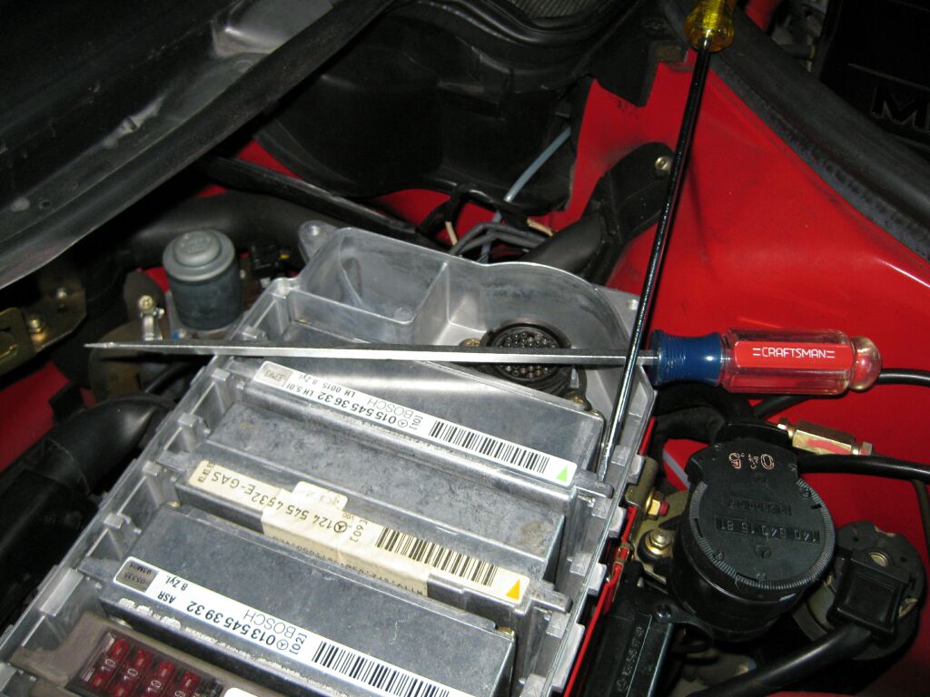 Since
I don't have the computer removal tool, I use two long flat blade screw
drivers like pictured to serve as a lever to pry out the ECU. Pry up a
little at each end till the ECU is free
Since
I don't have the computer removal tool, I use two long flat blade screw
drivers like pictured to serve as a lever to pry out the ECU. Pry up a
little at each end till the ECU is free
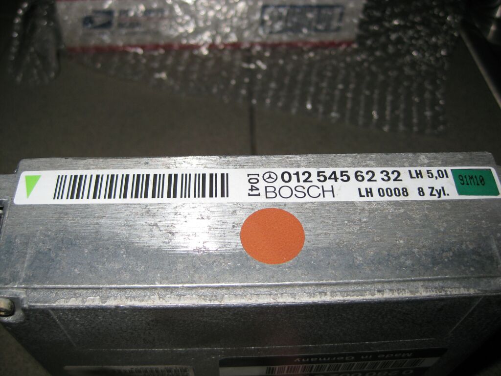
 Top
is the 92 ECU with a build date of Oct 1991 and below is the 93 ECU with a
build date of March 1993
Top
is the 92 ECU with a build date of Oct 1991 and below is the 93 ECU with a
build date of March 1993
 Once
the ECU is back in the CAN box, press it into place till it is fully seated.
I used a small rubber mallet to tap it into place. So far the car is
running good, but the real test is to get it back on the dyno and see if I
regained any of the missing hp.
Once
the ECU is back in the CAN box, press it into place till it is fully seated.
I used a small rubber mallet to tap it into place. So far the car is
running good, but the real test is to get it back on the dyno and see if I
regained any of the missing hp.
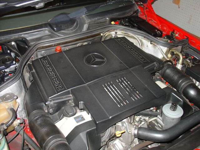
Engine Cooling Modification
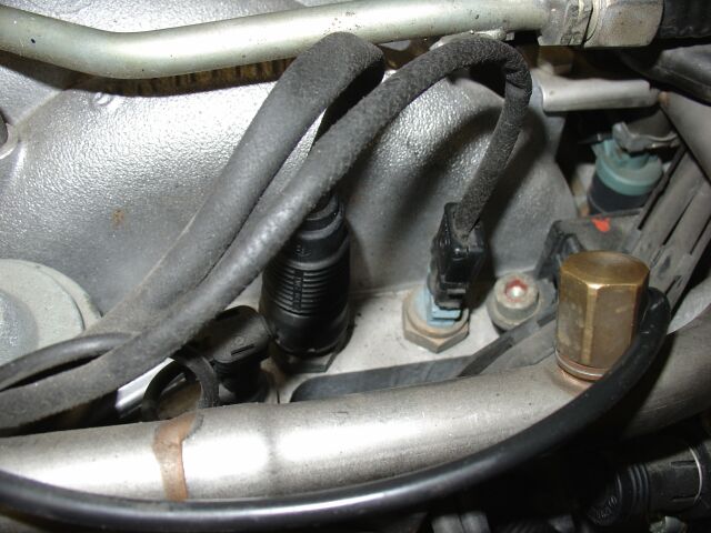 The
500E (along with many other MB models) runs very hot. One way to tackle
this problem is to add something like Redlines Watter Wetter to the coolant
tank. Another way is to modify the aux cooling fans so that they come on
earlier than 100 degrees. This can be done on cars that use an independent
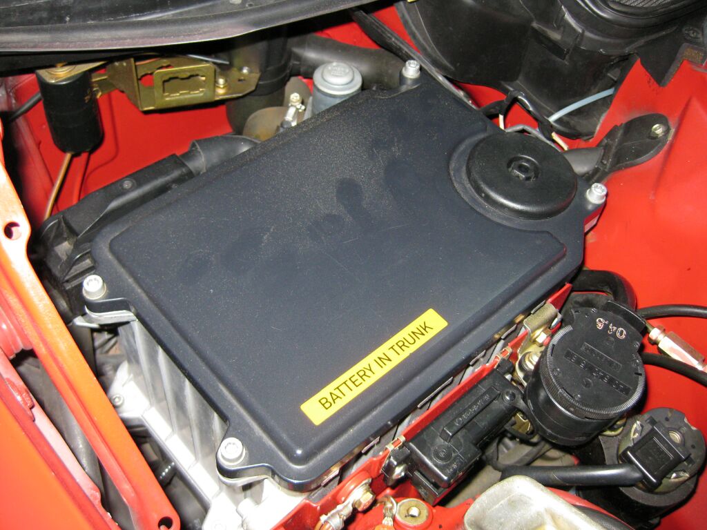
CTS sensor and a resister. Shown here is the CTS sensor on the M119, its
under the front engine cover (cover in front of the air cleaner assembly)
The
500E (along with many other MB models) runs very hot. One way to tackle
this problem is to add something like Redlines Watter Wetter to the coolant
tank. Another way is to modify the aux cooling fans so that they come on
earlier than 100 degrees. This can be done on cars that use an independent
CTS sensor and a resister. Shown here is the CTS sensor on the M119, its
under the front engine cover (cover in front of the air cleaner assembly)
 To
perform this modification, you need to install a resister across the CTS
contacts. Since this modification and additional details are already fully
documented on another MB owners site, I will refer you to his site. If you
don't feel included to perform this mod yourself, you can also purchase a
pre-made clip/resistor pack. Visit this site for more information.
http://pages.prodigy.net/jforgione/MB_CTS.html In case your wondering,
I am using a 1100 ohm resister that allows the fan to come on at 92 degrees.
This modification works great.
To
perform this modification, you need to install a resister across the CTS
contacts. Since this modification and additional details are already fully
documented on another MB owners site, I will refer you to his site. If you
don't feel included to perform this mod yourself, you can also purchase a
pre-made clip/resistor pack. Visit this site for more information.
http://pages.prodigy.net/jforgione/MB_CTS.html In case your wondering,
I am using a 1100 ohm resister that allows the fan to come on at 92 degrees.
This modification works great.
1st Gear Start
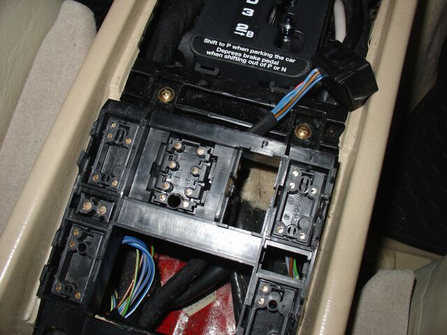
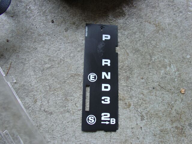 The
500E was designed by Mercedes to start in 2nd gear with the option of starting
in first gear under full throttle or by moving the shifter down to 2nd and then
to the right (B). There are several companies that sell 1st gear start
kits but I always wondered if it was really necessary to pay someone for this
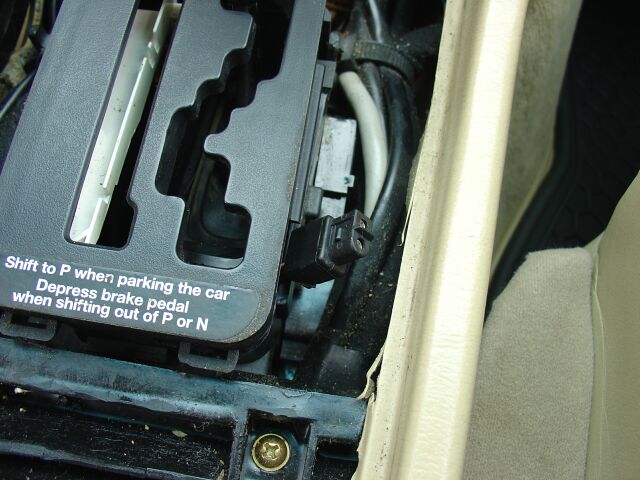
feature. I started out by taking apart the shifter console to get access
to the mechanism that engages first gear start.
The
500E was designed by Mercedes to start in 2nd gear with the option of starting
in first gear under full throttle or by moving the shifter down to 2nd and then
to the right (B). There are several companies that sell 1st gear start
kits but I always wondered if it was really necessary to pay someone for this
feature. I started out by taking apart the shifter console to get access
to the mechanism that engages first gear start.
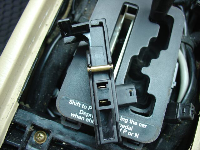
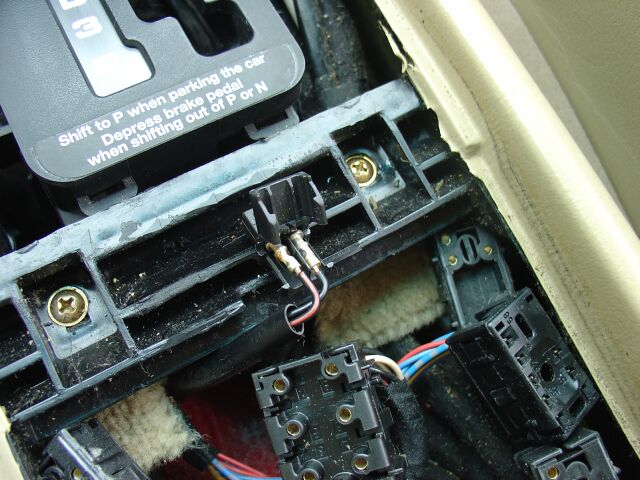
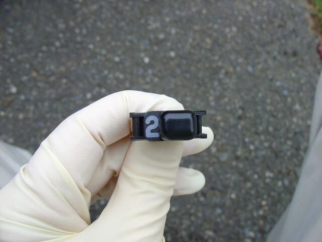
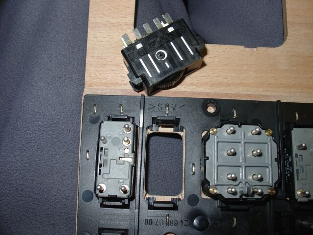
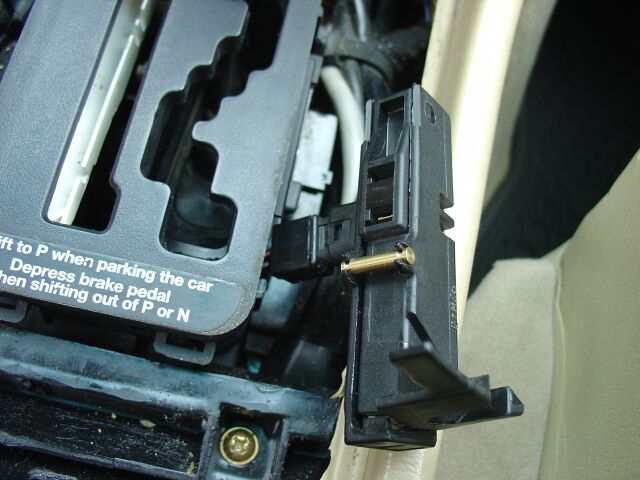 With
the factory shifter, it can be tricky to maneuver the shifter gate up and out of
the way. In this picture you can see what the 1st gear start switch looks
like. I was expecting a momentary switch, but this one is basic on/off
type of switch, when you move the shift level into 2nd, then over to B (to
engage a 1st gear start), you see the switch move, complete the ckt and then
when the shifter moves back to 2nd, the 1st gear ckt is opened again. With
the switch out and engaged (closed ckt) the car always starts in first!
With
the factory shifter, it can be tricky to maneuver the shifter gate up and out of
the way. In this picture you can see what the 1st gear start switch looks
like. I was expecting a momentary switch, but this one is basic on/off
type of switch, when you move the shift level into 2nd, then over to B (to
engage a 1st gear start), you see the switch move, complete the ckt and then
when the shifter moves back to 2nd, the 1st gear ckt is opened again. With
the switch out and engaged (closed ckt) the car always starts in first!
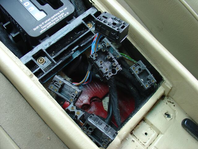
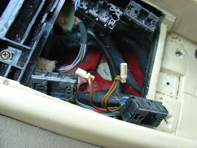
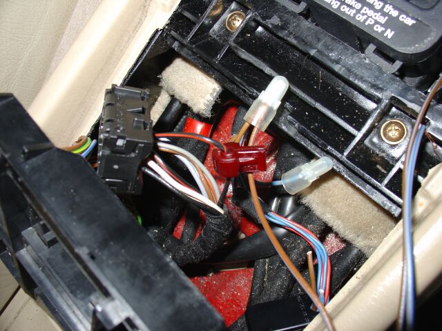
 I
could of just left the switch in the closed position and tucked it back inside
the console, but I wanted the ability to switch between 1st gear start and 2nd
gear start, so I unplugged the switch and pulled the wire harness down and out
where the window switches reside. I then reinstalled the now
non-functional 1st gear start switch, mainly to fill a small gap that could
collect dust and other garbage.
I
could of just left the switch in the closed position and tucked it back inside
the console, but I wanted the ability to switch between 1st gear start and 2nd
gear start, so I unplugged the switch and pulled the wire harness down and out
where the window switches reside. I then reinstalled the now
non-functional 1st gear start switch, mainly to fill a small gap that could
collect dust and other garbage.
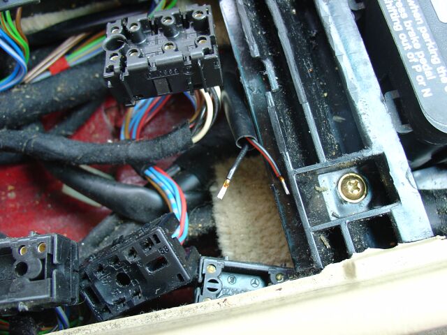
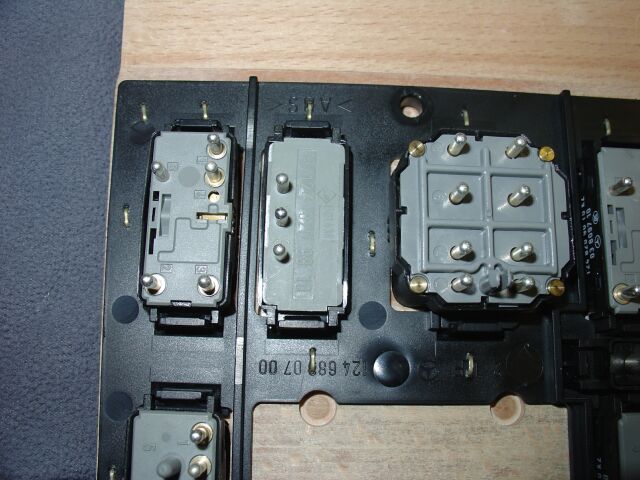
 This
is the other side of the 1st gear start switch.
This
is the other side of the 1st gear start switch.
 Since
I need the now useless fader location for a ASR defeat switch (coming soon!) the
only other non-essential switch location I could use is the rear window child
safety switch. I don't need that function and it will provide me with a
simple on/off switch to use for the 1st gear start.
Since
I need the now useless fader location for a ASR defeat switch (coming soon!) the
only other non-essential switch location I could use is the rear window child
safety switch. I don't need that function and it will provide me with a
simple on/off switch to use for the 1st gear start.
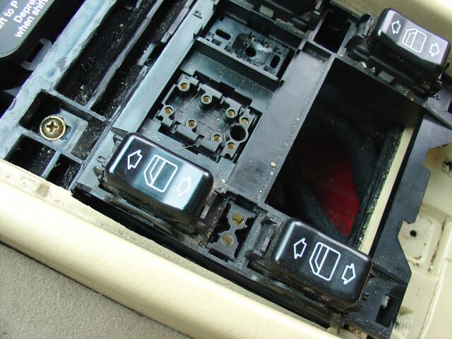
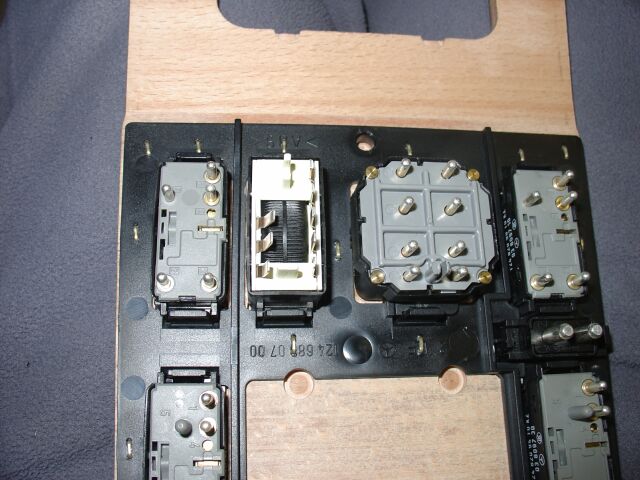
Of course, you have to take all the switch's out and then remove all the switch
holders from the tray. I needed to remove the female pins from the child
safety switch holder so I could bridge them together (otherwise the passengers
in the rear seats won't be able to open the windows)
 To
keep this modification easily reversible, I elected to bridge these two pins
together using a male-male plug, it was then shrink wrapped and tucked back into
the console.
To
keep this modification easily reversible, I elected to bridge these two pins
together using a male-male plug, it was then shrink wrapped and tucked back into
the console.
 This
is the child safety switch holder, without the pins. The pins used for
this switch are the same used for the headlights, and I just so happened to have
some of these around (left over from a euro headlight upgrade to my W201)
This
is the child safety switch holder, without the pins. The pins used for
this switch are the same used for the headlights, and I just so happened to have
some of these around (left over from a euro headlight upgrade to my W201)
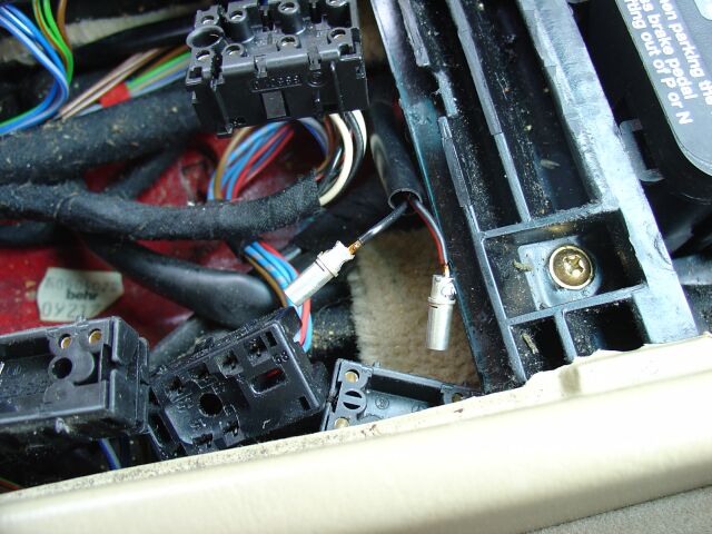
 This
is the 1st gear start plug and its pins, much smaller than the pins used on the
child safety switch
This
is the 1st gear start plug and its pins, much smaller than the pins used on the
child safety switch
 Once
I reached this point, I reassembled the shifter console with the now,
non-functional 1st ear start switch
Once
I reached this point, I reassembled the shifter console with the now,
non-functional 1st ear start switch
 I
elected to de-solder these pins and save them (along with the plastic holder) in
the event I want to restore everything back to factory.
I
elected to de-solder these pins and save them (along with the plastic holder) in
the event I want to restore everything back to factory.
 Since
I happened to have some adhesive letters laying around, I modified a number 2 to
fit over the pictogram of the child, so when in this position, it will now show
a number 2 (to indicate the ckt is open and the car will start in 2nd gear)
Since
I happened to have some adhesive letters laying around, I modified a number 2 to
fit over the pictogram of the child, so when in this position, it will now show
a number 2 (to indicate the ckt is open and the car will start in 2nd gear)
 Now
in the process of de-soldering the originally small pins and replacing them with
the larger headlight pins
Now
in the process of de-soldering the originally small pins and replacing them with
the larger headlight pins
 Here
are the larger pins installed. Although this picture shows the wires
coming out from the ends of the pins, you actually have to insert the wires from
the sides, otherwise the end caps of the pin holder won't close (I removed these
and did it correctly AFTER I discovered my error).
Here
are the larger pins installed. Although this picture shows the wires
coming out from the ends of the pins, you actually have to insert the wires from
the sides, otherwise the end caps of the pin holder won't close (I removed these
and did it correctly AFTER I discovered my error).
 Once
I reached this point, I installed the switch and took the car for several short
drives and then out on the freeway. I was afraid with this ckt closed, the
transmission might not shift correctly, but so far there everything is working
fine (you don't have any control over the shift points using my method, so 1st
to 2nd shifts happen around 4500 rpm, the aftermarket kits allow you to adjust
this shift point)
Once
I reached this point, I installed the switch and took the car for several short
drives and then out on the freeway. I was afraid with this ckt closed, the
transmission might not shift correctly, but so far there everything is working
fine (you don't have any control over the shift points using my method, so 1st
to 2nd shifts happen around 4500 rpm, the aftermarket kits allow you to adjust
this shift point)
 This
is how the child safety switch looks now, with the number 2 on it.
This
is how the child safety switch looks now, with the number 2 on it.
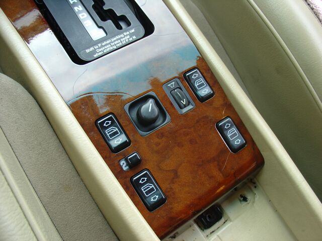 Here
is the console back together and my newly refinish center console wood trim
(more on that later). I am really loving my 1st gear start but now I need
to get motivated and install the ASR bypass to compliment this modification. (my
ASR mode will be similar, it will not be using someone else's kit, a switch and
a few relays are all you need.....stay tuned!)
Here
is the console back together and my newly refinish center console wood trim
(more on that later). I am really loving my 1st gear start but now I need
to get motivated and install the ASR bypass to compliment this modification. (my
ASR mode will be similar, it will not be using someone else's kit, a switch and
a few relays are all you need.....stay tuned!)
5-09-06 - Renntech 1st Gear Start Valve Body
 This
is the newest toy recently received. It is a Renntech modified 1st gear
start transmission valve body. With this installed, the 500E will always
start in 1st gear. This install is a bit tricky, so I will be enlisting my
friend
Steve Geyer to provide his expertise.
Renntech's installation instructions
This
is the newest toy recently received. It is a Renntech modified 1st gear
start transmission valve body. With this installed, the 500E will always
start in 1st gear. This install is a bit tricky, so I will be enlisting my
friend
Steve Geyer to provide his expertise.
Renntech's installation instructions
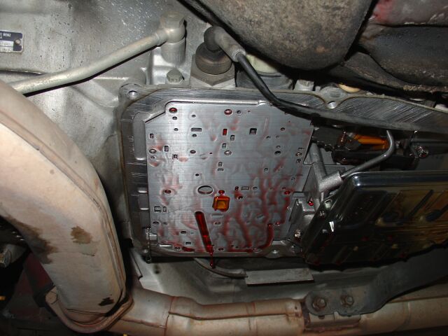
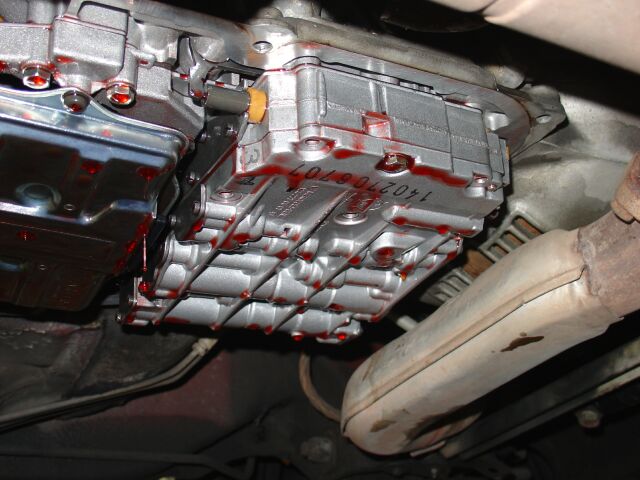 To
do the valve body swap requires a little over 4 quarts of trans fluid, since I
recently just had the fluid/filter changed, I picked up enough fluid just to do
the valve body swap.
To
do the valve body swap requires a little over 4 quarts of trans fluid, since I
recently just had the fluid/filter changed, I picked up enough fluid just to do
the valve body swap.
 This
swap does not appear to be to complicated, but I recommend you have someone with
a expert knowledge of MB and/or transmissions do this swap for you.
This
swap does not appear to be to complicated, but I recommend you have someone with
a expert knowledge of MB and/or transmissions do this swap for you.
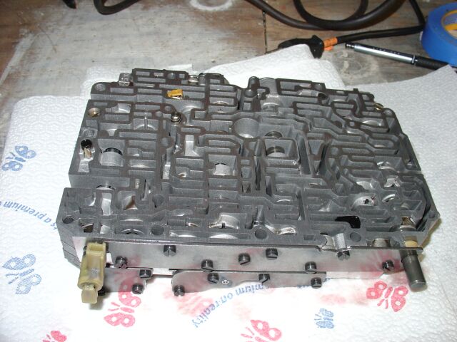
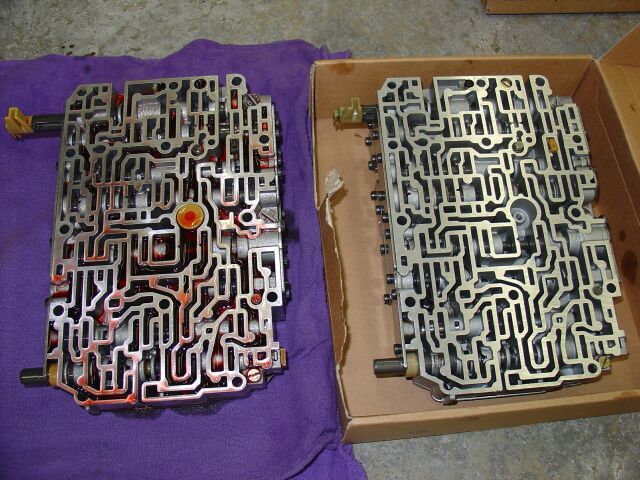 On
the left is the original valve body dated 1993, on the right is the Renntech
valve body dated 1999. The center yellow valve/spring was installed on the
Renntech valvebody (probably was lost in transit) and from the outside, its hard
to differentiate any difference between the two. The Renntech has one
spring valve in the right hand bottom corner that does not appear to move
compared to the OE valve body, so its possible that this is part of their
modification to make the valve body start the car in 1st gear. What a
incredible modification this is, it really breaths new life into the 500e.
Steve made several adjustments to adjust the shifting, so it shifts very
quickly.
On
the left is the original valve body dated 1993, on the right is the Renntech
valve body dated 1999. The center yellow valve/spring was installed on the
Renntech valvebody (probably was lost in transit) and from the outside, its hard
to differentiate any difference between the two. The Renntech has one
spring valve in the right hand bottom corner that does not appear to move
compared to the OE valve body, so its possible that this is part of their
modification to make the valve body start the car in 1st gear. What a
incredible modification this is, it really breaths new life into the 500e.
Steve made several adjustments to adjust the shifting, so it shifts very
quickly.
After my
transmission failed, I had it replaced with a fully rebuilt and re-engineered
version. To maintain the warranty, I couldn't use the Renntech valve body,
so I sold it and installed a electronic FGS module. I bought one from
www.fgsswitch.com and you can see
pictures of my car under the 500e installation section
 This
is the FGS module as shipped to me, do remember that mine was more or less a
pre-production model, much has changed in the newer modules, visit the site and
read up on it.
This
is the FGS module as shipped to me, do remember that mine was more or less a
pre-production model, much has changed in the newer modules, visit the site and
read up on it.
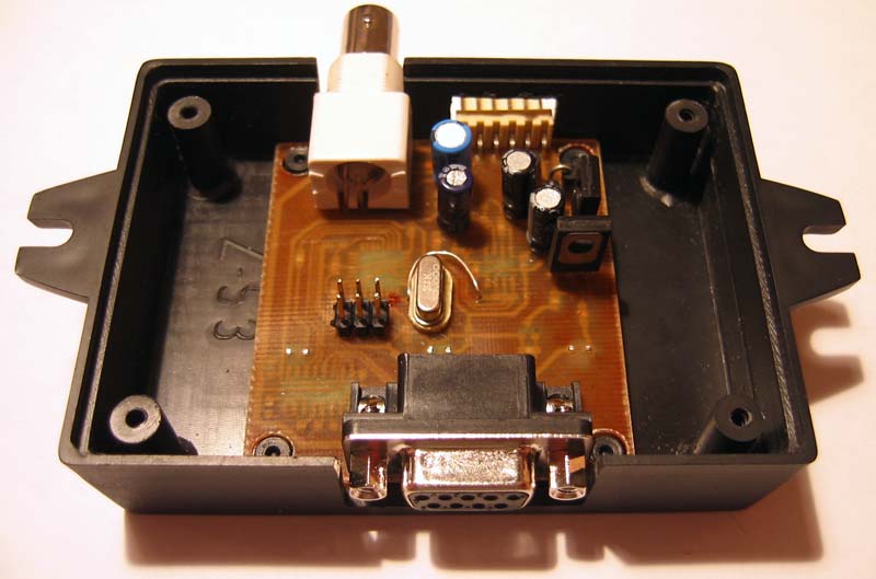 This
is the inside of the FGS module, which uses a coax interface cable to the front
ABS sensor and has serial interface for programming via a laptop computer.
This
is the inside of the FGS module, which uses a coax interface cable to the front
ABS sensor and has serial interface for programming via a laptop computer.
 The
coax interface cable is routed up from the transmission tunnel to a grommet on
the drivers side, you see the cable pulled through the factory grommet here.
The
coax interface cable is routed up from the transmission tunnel to a grommet on
the drivers side, you see the cable pulled through the factory grommet here.
 With
the cable routed up into the engine bay, you need to solder your coax fittings
onto the end of the cable.
With
the cable routed up into the engine bay, you need to solder your coax fittings
onto the end of the cable.
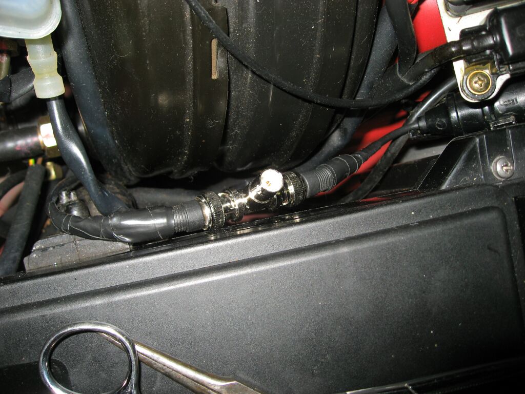 This
is where the front ABS coax cable is located, so we need to cut it and
splice/solder new ends, so we can use the included T coupler. The FGS coax
will connect to the open spot on the T.
This
is where the front ABS coax cable is located, so we need to cut it and
splice/solder new ends, so we can use the included T coupler. The FGS coax
will connect to the open spot on the T.
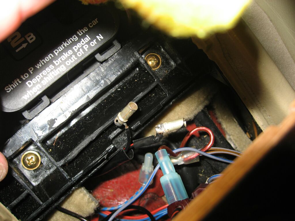 On
the inside, you need to locate your first gear start wires, on the 500e, they
are attached to a switch that under the shifter, indicated by the B. Mine
were already pulled out because of the earlier FGS window switch mod I did a
year or so before.
On
the inside, you need to locate your first gear start wires, on the 500e, they
are attached to a switch that under the shifter, indicated by the B. Mine
were already pulled out because of the earlier FGS window switch mod I did a
year or so before.
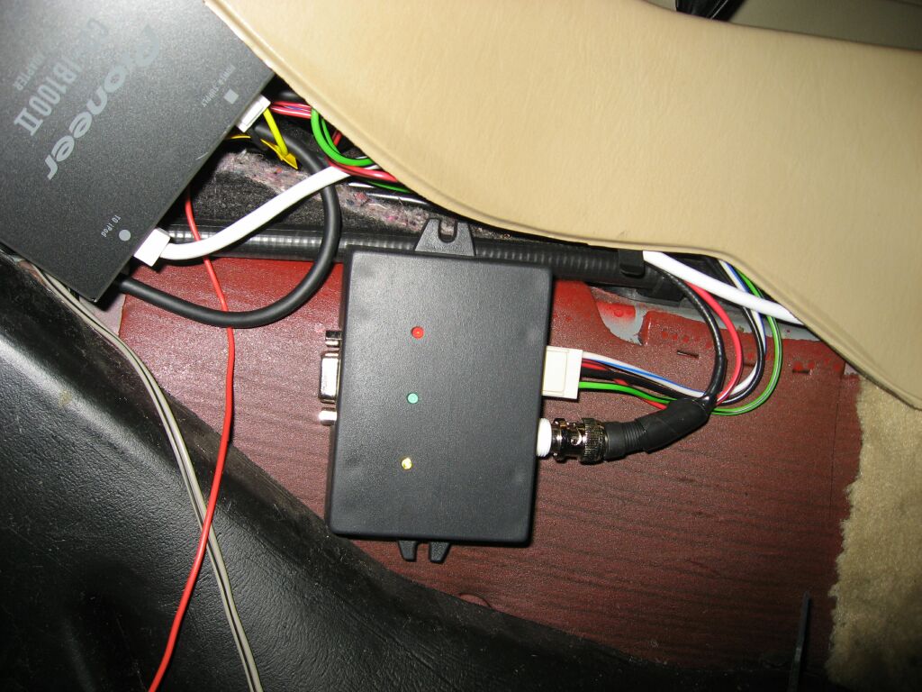 I
mounted the FGS module on the transmission tunnel, next to my IPod interface
I
mounted the FGS module on the transmission tunnel, next to my IPod interface
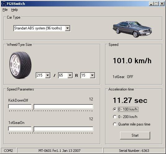 You
use a laptop to program the FGS module. You can tell it the size of
tire/wheel you have and adjust when the FGS module engages and disengages.
You can also measure your speed and acceleration time.
You
use a laptop to program the FGS module. You can tell it the size of
tire/wheel you have and adjust when the FGS module engages and disengages.
You can also measure your speed and acceleration time.
4-1-06 - ASR
Defeat Installation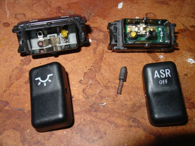
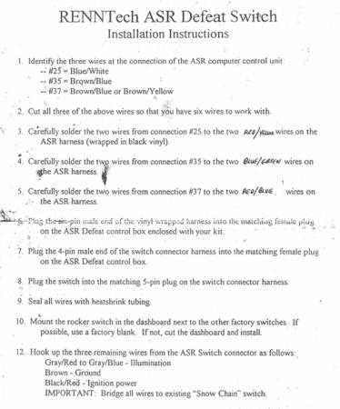
In preparation of installing a on/off function for the ASR, I needed an
actual ASR off switch from a R129, but these are only a momentary on/off,
so I had to pick up a extra rear dome light switch and swap the covers.
The cover of the ASR switch does not accept the little spring rod, so you have
to carefully file out the hole till the spring rod slides in/out easily.
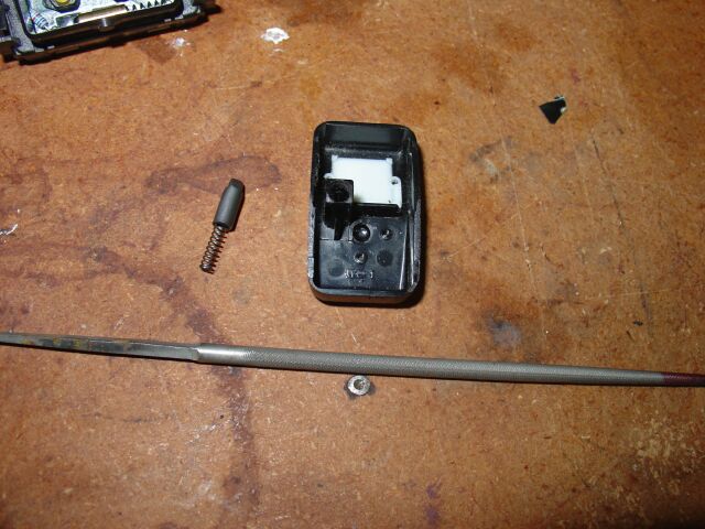 I
used a small round file to carefully enlarge the spring rod hold on the ASR
cover.
I
used a small round file to carefully enlarge the spring rod hold on the ASR
cover.
 The
next step here is to take the switch completely apart. Because we need a
+12 to trigger our relays, the switch as is will not work. If we move some
of our wires around, we can get the switch to work, but the LED will not
illuminate. So as you can see from this picture, we are going to use pin 1
for ground, pin 2 for switch +12 and pin 3 is switch +12 to the relays.
The
next step here is to take the switch completely apart. Because we need a
+12 to trigger our relays, the switch as is will not work. If we move some
of our wires around, we can get the switch to work, but the LED will not
illuminate. So as you can see from this picture, we are going to use pin 1
for ground, pin 2 for switch +12 and pin 3 is switch +12 to the relays.
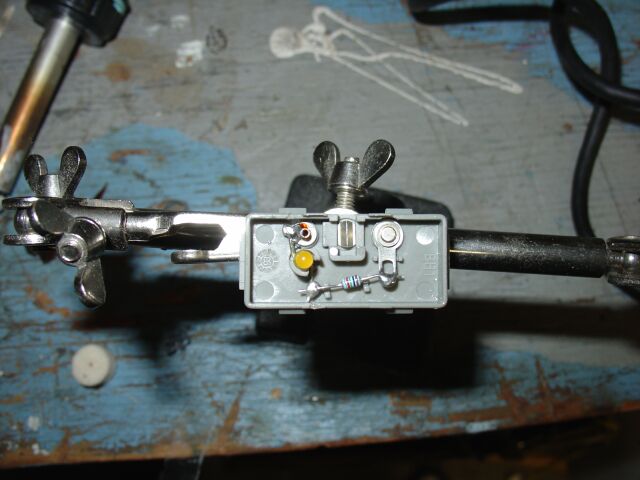 With
the switch apart and mounted in a small electronics vice, our next step is toe
reverse the +/- leads of the LED. This will allow the LED to light when
the ASR is off. Use a solder gun to loosen the solder and carefully remove
the LED from the holder, be careful re-bending the LED wires and re-insert into
the holder. Solder the leads back and you will be done.
With
the switch apart and mounted in a small electronics vice, our next step is toe
reverse the +/- leads of the LED. This will allow the LED to light when
the ASR is off. Use a solder gun to loosen the solder and carefully remove
the LED from the holder, be careful re-bending the LED wires and re-insert into
the holder. Solder the leads back and you will be done.
Once you have the hold enlarged and the spring rod moves freely, you can install
the ASR cover on the rear dome light switch. When I picked up the rear dome light switch, I requested the socket and a length of
wire to work with. This will help facilitate the installation of
the switch. Thanks to Livin_it_up on the 190rev for
hooking me up with the switch and B-pillars.
picked up the rear dome light switch, I requested the socket and a length of
wire to work with. This will help facilitate the installation of
the switch. Thanks to Livin_it_up on the 190rev for
hooking me up with the switch and B-pillars.
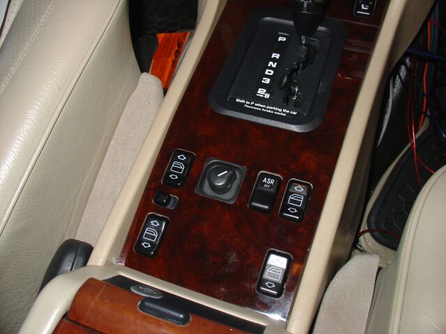
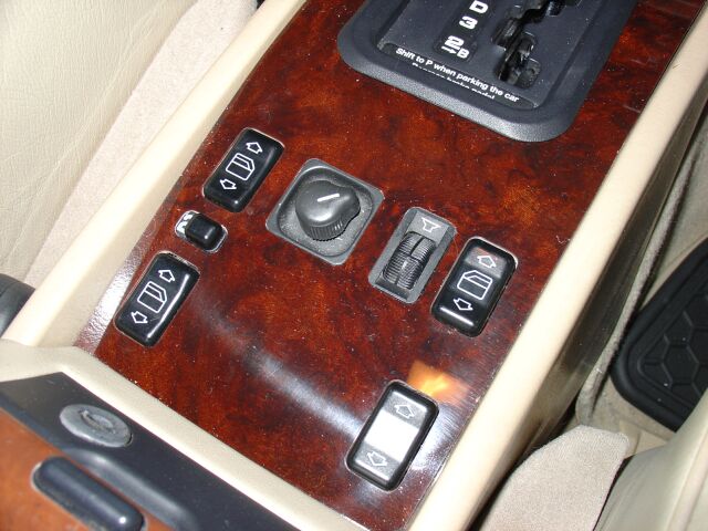 A
ideal spot for our newly created ASR off switch is the center console fader
location. If you have a aftermarket stereo, most likely this switch has
been bypassed.
A
ideal spot for our newly created ASR off switch is the center console fader
location. If you have a aftermarket stereo, most likely this switch has
been bypassed.
 With
the center console wood removed and all the switch's disconnected, were ready to
remove the OE fader switch and install our ASR off switch.
With
the center console wood removed and all the switch's disconnected, were ready to
remove the OE fader switch and install our ASR off switch.
 Be
careful popping the switch out of its holder. I use a small flat blade
screwdriver to assist.
Be
careful popping the switch out of its holder. I use a small flat blade
screwdriver to assist.
 Here
is the ASR off switch snapped into place. You will notice that the switch
is not as deep as the fader, this creates a new problem that we need to address.
Here
is the ASR off switch snapped into place. You will notice that the switch
is not as deep as the fader, this creates a new problem that we need to address.
 You
need to remove the old fader switch socket. The next step depends upon how
you are going to wire up your new ASR off switch. When I purchased my rear
dome light switch, I also requested the matching socket and a length of wire.
I was hoping it would mount into the fader switch location (which it did) but
because the fader switch is deeper than the ASR off switch, you can't mount the
socket into the switch assembly. So before you reassemble the console,
remember to plug your ASR off switch socket into the switch.
You
need to remove the old fader switch socket. The next step depends upon how
you are going to wire up your new ASR off switch. When I purchased my rear
dome light switch, I also requested the matching socket and a length of wire.
I was hoping it would mount into the fader switch location (which it did) but
because the fader switch is deeper than the ASR off switch, you can't mount the
socket into the switch assembly. So before you reassemble the console,
remember to plug your ASR off switch socket into the switch.
 Moving
on to the relays, we need to locate a suitable source of switched +12 and a
ground. I located these connected to the old fader switch wire harness, so
I tapped into them and ran a short length of wire up to the ash tray area.
Moving
on to the relays, we need to locate a suitable source of switched +12 and a
ground. I located these connected to the old fader switch wire harness, so
I tapped into them and ran a short length of wire up to the ash tray area.
 What
we need are three SPDT relays, one for each ASR wire you will be splicing into.
When the relays are off, the circuit is open, allowing the ASR wires to connect
and ASR to work normally. When energized, the relays break the connections
of these three wires. This is the preferred method IMO to wire this up.
In the event of a relay failure, your ASR off switch just will not turn the ASR
off.
What
we need are three SPDT relays, one for each ASR wire you will be splicing into.
When the relays are off, the circuit is open, allowing the ASR wires to connect
and ASR to work normally. When energized, the relays break the connections
of these three wires. This is the preferred method IMO to wire this up.
In the event of a relay failure, your ASR off switch just will not turn the ASR
off.
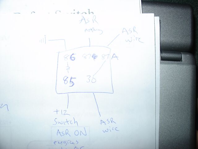 Although
this is just my scribbled notes on the relay configuration, this is the diagram
I used to wire up each of the three relays. You can see that in the
un-energized state, ASR functions normal and when energized, the connections are
broken.
Although
this is just my scribbled notes on the relay configuration, this is the diagram
I used to wire up each of the three relays. You can see that in the
un-energized state, ASR functions normal and when energized, the connections are
broken.
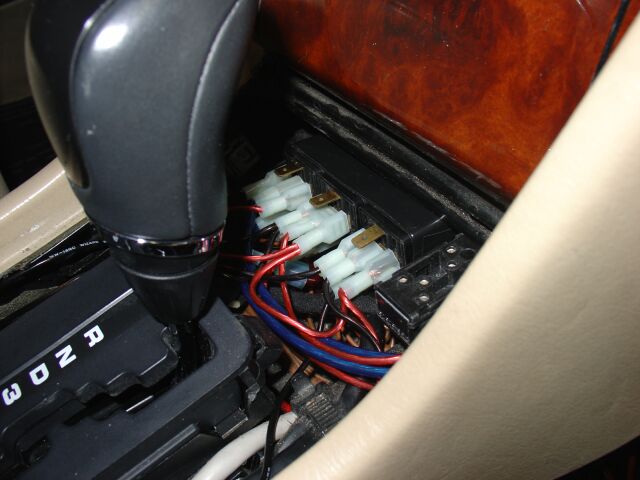 I
created a wire harness using black, blue and red 16 awg wire (two of each color)
and wired them up to the relay (using the diagram above). I located the
relays up under the ash tray and routed the wire harness out the rear of the
console, up under the passenger side dash and into the kick panel on the
passenger side. You can not fit your hand up into the opening under the
kick panel, so I ran a "pull" wire from the engine bay, grabbed it using some
long pliers and attached it to my wire harness and then pulled the wire harness
up into the engine bay from the engine bay.
I
created a wire harness using black, blue and red 16 awg wire (two of each color)
and wired them up to the relay (using the diagram above). I located the
relays up under the ash tray and routed the wire harness out the rear of the
console, up under the passenger side dash and into the kick panel on the
passenger side. You can not fit your hand up into the opening under the
kick panel, so I ran a "pull" wire from the engine bay, grabbed it using some
long pliers and attached it to my wire harness and then pulled the wire harness
up into the engine bay from the engine bay.
Since
we were done in the console, I put it back together (remembering to plug my ASR
off harness socket in). At this point, you should of already tested the
switch and the function of the relays. You should see the ASR off switch
illuminate when its switched off and you should hear the relays click. I
tested the relay function using my VOM, with the positive connected to one end
of my wire pair and the negative connected to the other. You should see
your VOM display change as you switch the ASR off/on. Test each pair
before you put the console back together.
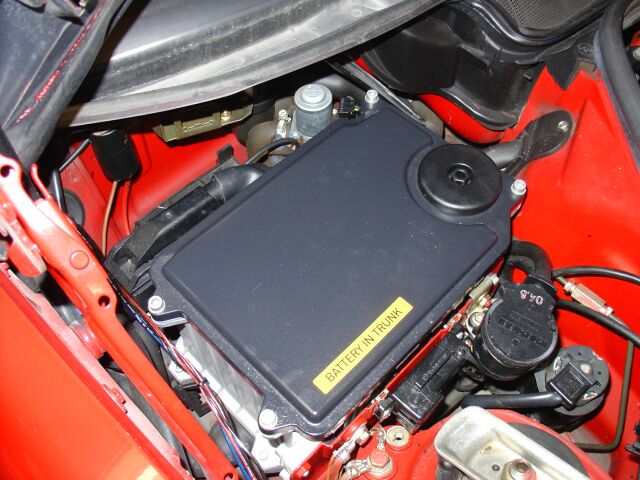
 This
is the location I chose to pull my wire harness up into the engine bay through.
You can use a small Exacto knife to cut our the plug from this rubber grommet.
I then fed a single wire down through the hole and located that wire from the
kick panel side. Remember, you need something long that you can grab the
"pull" wire with. I then taped the wire harness to the "pull" wire and
pulled it up into the engine bay and through the rubber grommet.
This
is the location I chose to pull my wire harness up into the engine bay through.
You can use a small Exacto knife to cut our the plug from this rubber grommet.
I then fed a single wire down through the hole and located that wire from the
kick panel side. Remember, you need something long that you can grab the
"pull" wire with. I then taped the wire harness to the "pull" wire and
pulled it up into the engine bay and through the rubber grommet.
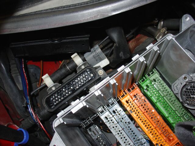
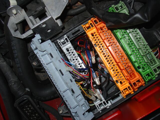
 With
the harness now pulled up into the engine bay, its time to take apart the can
box. You need to remove the cover, all the computers and the silver
aluminum housing. Your going to need a selection of torx bits, sockets and
some screw drivers to do this. Take your time as some of these torx screws
are in hard to reach areas and if you drop one, they have a tendency to
disappear.
With
the harness now pulled up into the engine bay, its time to take apart the can
box. You need to remove the cover, all the computers and the silver
aluminum housing. Your going to need a selection of torx bits, sockets and
some screw drivers to do this. Take your time as some of these torx screws
are in hard to reach areas and if you drop one, they have a tendency to
disappear.
 Since
I don't have the official MB tool for pulling the computers, you need to
improvise. You can see that I used a single screw driver as a lever rest
and another as the lever. Gently pry at each end of the computer till it
pops loose, so a little at each end, you don't want to wedge it at a angle.
Since
I don't have the official MB tool for pulling the computers, you need to
improvise. You can see that I used a single screw driver as a lever rest
and another as the lever. Gently pry at each end of the computer till it
pops loose, so a little at each end, you don't want to wedge it at a angle.
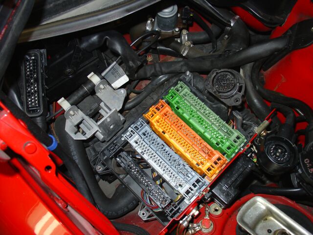
 Once
your computers are all out, you can remove the can box. This item needs to
be removed from its clips and moved out of the way, same is true for the main
harness connector. The harness connector has a lever that if you pull it
up, it will pop the connector out of the harness, move both of these out of your
work area.
Once
your computers are all out, you can remove the can box. This item needs to
be removed from its clips and moved out of the way, same is true for the main
harness connector. The harness connector has a lever that if you pull it
up, it will pop the connector out of the harness, move both of these out of your
work area.
 You
can see that this bracket has two 10 mm bolts that need to be removed before the
can housing can be removed.
You
can see that this bracket has two 10 mm bolts that need to be removed before the
can housing can be removed.
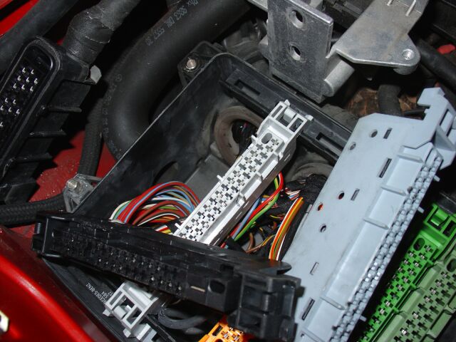
 Once
you have all the bolts and torx screws removed, carefully lift up the can box
assembly. Its wedged in tight, so you may have to wiggle it back/forth a
bit to get it to lift up. You need to do this step as the can box sits
over these little clips you need to release so the computer sockets can be
lifted up.
Once
you have all the bolts and torx screws removed, carefully lift up the can box
assembly. Its wedged in tight, so you may have to wiggle it back/forth a
bit to get it to lift up. You need to do this step as the can box sits
over these little clips you need to release so the computer sockets can be
lifted up.
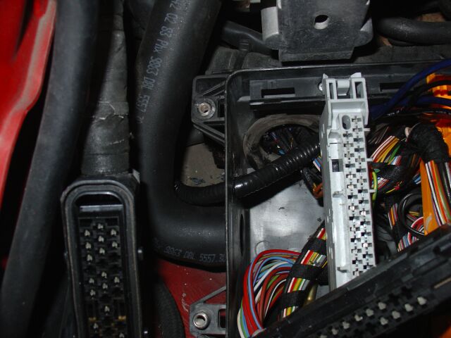
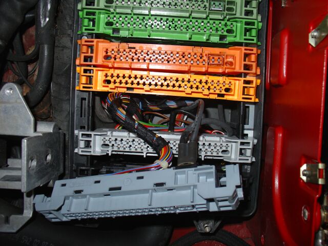 I
used a small flat blade screw driver to release the small clips (located at each
end of the computer socket). You need to lift up the ASR computer socket,
shown here in this picture. You also need to strip back some of the tape
holding the wires together.
I
used a small flat blade screw driver to release the small clips (located at each
end of the computer socket). You need to lift up the ASR computer socket,
shown here in this picture. You also need to strip back some of the tape
holding the wires together.
 Before
you move on, now is a good time to make a hole in the can box plastic base, for
your newly created wire harness. I chose a spot directly above the hot air
intake hole. I used a unibit and a right angle cordless drill to cut my
hole. I drilled it just large enough to accommodate my wire harness
encased (and wrapped in electrical tape) in loom wrap.
Before
you move on, now is a good time to make a hole in the can box plastic base, for
your newly created wire harness. I chose a spot directly above the hot air
intake hole. I used a unibit and a right angle cordless drill to cut my
hole. I drilled it just large enough to accommodate my wire harness
encased (and wrapped in electrical tape) in loom wrap.

Here you can see my wire harness fitted through the newly drilled hole.
You need to pop up some of the other computer sockets to get enough room to do
this and to route your new wires over to the correct spot.
 This
is the wire harness in loom and wrapped with electrical tape. It was
routed under the cooling hose so its out of sight and out of the way. You
can put the computers sockets back in once you have your harness routed over to
the ASR socket location.
This
is the wire harness in loom and wrapped with electrical tape. It was
routed under the cooling hose so its out of sight and out of the way. You
can put the computers sockets back in once you have your harness routed over to
the ASR socket location.
 The
wires we need to locate are 25, 35 and 37.
Renntech's instructions
indicate that these should be 25 - Blue/White, 35 - Brown/Blue and 37 -
Brown/Blue or Brown/Yellow. On my 5/93 built 500E, the actual colors were
25 - Blue, 35 - Brown/Yellow and 37 - Brown/Green. On the bottom of the
socket, the numbers are listed. I verified this by also looking at the
bottom of the ASR computer and I triple checked before I cut any of the wires.
I have additional Renntech instructions and other ASR information under my
Techdocs section. Note
that there is one hand written ASR relay diagram, its not the diagram I used.
The
wires we need to locate are 25, 35 and 37.
Renntech's instructions
indicate that these should be 25 - Blue/White, 35 - Brown/Blue and 37 -
Brown/Blue or Brown/Yellow. On my 5/93 built 500E, the actual colors were
25 - Blue, 35 - Brown/Yellow and 37 - Brown/Green. On the bottom of the
socket, the numbers are listed. I verified this by also looking at the
bottom of the ASR computer and I triple checked before I cut any of the wires.
I have additional Renntech instructions and other ASR information under my
Techdocs section. Note
that there is one hand written ASR relay diagram, its not the diagram I used.
 Once
you locate each of the correct wires, cut them and splice in your wire harness.
Use both of your blue wires for one of the ASR wires and so on. You can
solder your connections or use crimp caps, I don't recommend any other methods
for securing your connections.
Once
you locate each of the correct wires, cut them and splice in your wire harness.
Use both of your blue wires for one of the ASR wires and so on. You can
solder your connections or use crimp caps, I don't recommend any other methods
for securing your connections.
 Before
I started putting everything back together, I ran a bead of silicone around my
new wire harness, you need to make sure this is sealed very well. Moisture
is not something you want getting to your computers. Your computer sockets
will snap back into place and the reassembly is the reverse of the disassembly.
This is a very worth wile modification, combined with a 1st gear start, you have
unleashed the monster in your 500E.
Before
I started putting everything back together, I ran a bead of silicone around my
new wire harness, you need to make sure this is sealed very well. Moisture
is not something you want getting to your computers. Your computer sockets
will snap back into place and the reassembly is the reverse of the disassembly.
This is a very worth wile modification, combined with a 1st gear start, you have
unleashed the monster in your 500E.
Custom Performance Exhaust 5-28-06
 In
the pursuit of elusive performance gains, I decided to finally bite the bullet,
drop some weight and free up the flow of exhaust gases. Trying to source
AMG or Brabus exhaust parts is difficult and expensive, so this time around, I
relied upon my local shop (Dan Fast) to build me a custom exhaust matched to my
vehicle. I chose to use a set of Magnaflow twin, square exhaust tips
(similar to the AMG style)
In
the pursuit of elusive performance gains, I decided to finally bite the bullet,
drop some weight and free up the flow of exhaust gases. Trying to source
AMG or Brabus exhaust parts is difficult and expensive, so this time around, I
relied upon my local shop (Dan Fast) to build me a custom exhaust matched to my
vehicle. I chose to use a set of Magnaflow twin, square exhaust tips
(similar to the AMG style)
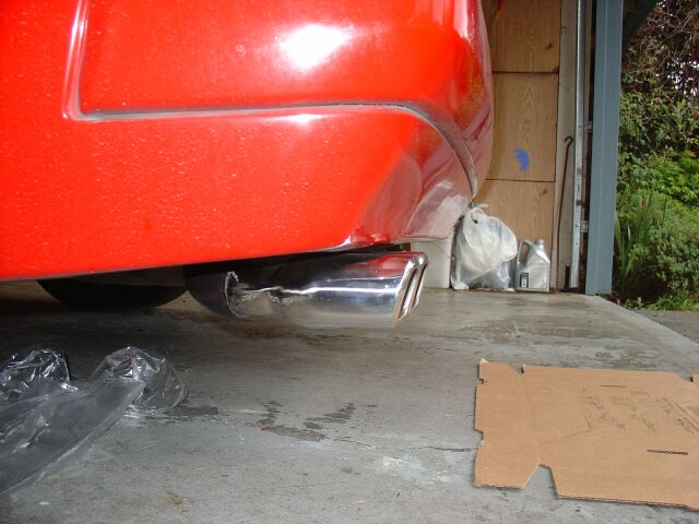 I
did not want to cut my bumper valance this time, so I had the tips mounted about
1/2" below the bottom valance and aligned over the OE exhaust notch (on the
inside of the valance). These are stainless steel, polished to a high
luster, so their longevity is guaranteed.
I
did not want to cut my bumper valance this time, so I had the tips mounted about
1/2" below the bottom valance and aligned over the OE exhaust notch (on the
inside of the valance). These are stainless steel, polished to a high
luster, so their longevity is guaranteed.
 The
tips took a couple of try's to get aligned properly, with the 3" pipe from the
MagnaFlow Wide Open Performance muffler, it was tough to get the angle correct.
Several 90 degree pipe pieces needed to be welded together to get the desired
effect.
The
tips took a couple of try's to get aligned properly, with the 3" pipe from the
MagnaFlow Wide Open Performance muffler, it was tough to get the angle correct.
Several 90 degree pipe pieces needed to be welded together to get the desired
effect.
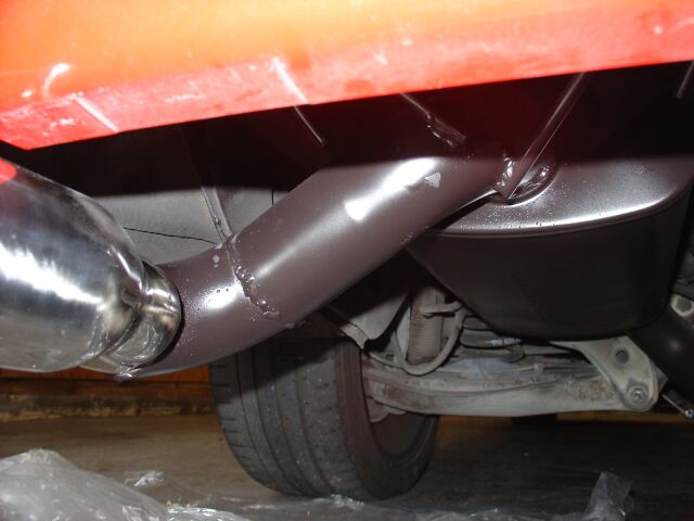
 The
tips do not protrude much from the bumper, which is just the way I wanted it.
The
tips do not protrude much from the bumper, which is just the way I wanted it.
 Here
you see the pipe coming from the cat and up into the MagnaFlow muffler.
All the pipe was painted with a high temp black paint. We started at the
pipe right before the cats and installed a high flow MagnaFlow two into one cat
(94057) and ran 3" pipe back to the muffler (11259) eliminating the heavy and
restrictive resonator.
Here
you see the pipe coming from the cat and up into the MagnaFlow muffler.
All the pipe was painted with a high temp black paint. We started at the
pipe right before the cats and installed a high flow MagnaFlow two into one cat
(94057) and ran 3" pipe back to the muffler (11259) eliminating the heavy and
restrictive resonator.
 You
can see the MagnaFlow muffler ere and how the 3" pipe needed several sections to
get the proper angle for the exhaust tips. The muffler was seated high up
into the OE muffler location and all OE mounting points were utilized. The
high flow cat is designed for V8 applications up to 378 cid or 6.2l and a gross
vehicle weight of 6000 lbs. This is the cat recommended for the 500e by
MagnaFlow (actually they recommended the same cat except with 2.5" out)
You
can see the MagnaFlow muffler ere and how the 3" pipe needed several sections to
get the proper angle for the exhaust tips. The muffler was seated high up
into the OE muffler location and all OE mounting points were utilized. The
high flow cat is designed for V8 applications up to 378 cid or 6.2l and a gross
vehicle weight of 6000 lbs. This is the cat recommended for the 500e by
MagnaFlow (actually they recommended the same cat except with 2.5" out)
 Here
is another angle of the rear muffler with custom tips, this bend was a bit
tricky, as I requested the tips to be mounted in notched OE location of the rear
bumper.
Here
is another angle of the rear muffler with custom tips, this bend was a bit
tricky, as I requested the tips to be mounted in notched OE location of the rear
bumper.
 Here
you can see the hangers added to the universal MagnaFlow muffler.
Here
you can see the hangers added to the universal MagnaFlow muffler.
 Another
picture showing the MagnaFlow muffler and the piping going back to the cat.
The sound of this design is as quiet as stock at idle and you really can only
notice a difference during acceleration, no resonance inside the cabin either.
The sound is very similar to my C5 Corvette with Borlas on it. I am very
pleased with the results
Another
picture showing the MagnaFlow muffler and the piping going back to the cat.
The sound of this design is as quiet as stock at idle and you really can only
notice a difference during acceleration, no resonance inside the cabin either.
The sound is very similar to my C5 Corvette with Borlas on it. I am very
pleased with the results
 You
can see the full Magnaflow muffler and custom hangers better in this picture.
You
can see the full Magnaflow muffler and custom hangers better in this picture.
 This
is the pipe section that goes from the rear Magnaflow muffler, up into the high
flow Maganflow catalytic converter.
This
is the pipe section that goes from the rear Magnaflow muffler, up into the high
flow Maganflow catalytic converter.
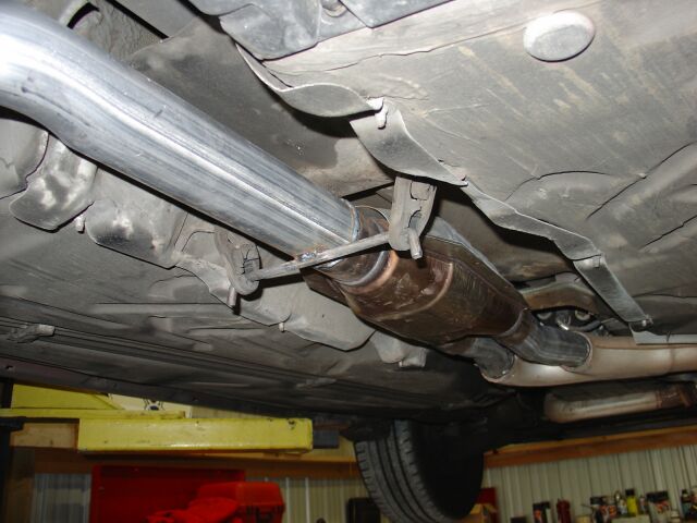
 This
is the spot that was chosen to start the new exhaust, right where the exhaust
manifolds merge and angle back under the car. The new catalytic converter
was located in the original spot with a small length of new pipe to connect it
to the OE pipe.
This
is the spot that was chosen to start the new exhaust, right where the exhaust
manifolds merge and angle back under the car. The new catalytic converter
was located in the original spot with a small length of new pipe to connect it
to the OE pipe.
 Another
angle of new exhaust from the rear muffler up to the catalytic converter.
Another
angle of new exhaust from the rear muffler up to the catalytic converter.
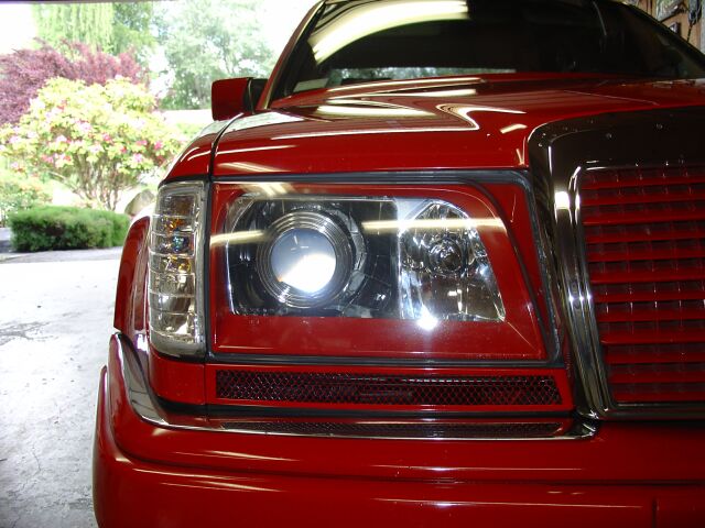
Air Intake Panel Modification - 5/25/06
 These
are the panels that mount under the headlights and normally have cut outs for
the wipers/squirters. This particular set is from a 300E 2.8, a model that
never came with headlight wipers, so no holes. This will be our base for
making vents that will allow more air to flow into the engine.
These
are the panels that mount under the headlights and normally have cut outs for
the wipers/squirters. This particular set is from a 300E 2.8, a model that
never came with headlight wipers, so no holes. This will be our base for
making vents that will allow more air to flow into the engine.
 So
the plan is to cut out a section of the panel and replace with some mesh to keep
debris out of the intake. This small home air intake vent was purchased at
Home Depot for about $2.50, it has enough mesh to complete our panel project.
So
the plan is to cut out a section of the panel and replace with some mesh to keep
debris out of the intake. This small home air intake vent was purchased at
Home Depot for about $2.50, it has enough mesh to complete our panel project.
 Using
a standard wire cutter, the frame was cut away, leaving me with just the mesh
material
Using
a standard wire cutter, the frame was cut away, leaving me with just the mesh
material
 Next
I needed to determine when to start/stop the vent opening and at what angles
would flow best with the headlights. As you can see, I mounted the panels
and determined that a straight vertical start point would be best on the left
and a angled cut that follows the angle of the headlight bezel on the right.
Next
I needed to determine when to start/stop the vent opening and at what angles
would flow best with the headlights. As you can see, I mounted the panels
and determined that a straight vertical start point would be best on the left
and a angled cut that follows the angle of the headlight bezel on the right.
 I
used a pencil and a straight edge square to measure my cut out. I made it
a little larger than what I wanted so filing would be necessary to get it exact.
This gives you a small margin for error when using the Dremel and cutting wheel.
I suggest the reinforced Dremel cutting wheels for this part of the project.
I
used a pencil and a straight edge square to measure my cut out. I made it
a little larger than what I wanted so filing would be necessary to get it exact.
This gives you a small margin for error when using the Dremel and cutting wheel.
I suggest the reinforced Dremel cutting wheels for this part of the project.
 After
about 30 minutes with a small file, the cuts were all smoothed out and slightly
beveled inward for more of a rounded appearance. I cut out the mesh so it
fit perfectly into the rear of the panel.
After
about 30 minutes with a small file, the cuts were all smoothed out and slightly
beveled inward for more of a rounded appearance. I cut out the mesh so it
fit perfectly into the rear of the panel.
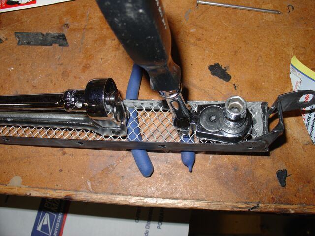
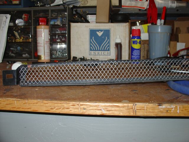 So
here is the mesh being test fitted and trimmed down so it sits flush into the
panel
So
here is the mesh being test fitted and trimmed down so it sits flush into the
panel
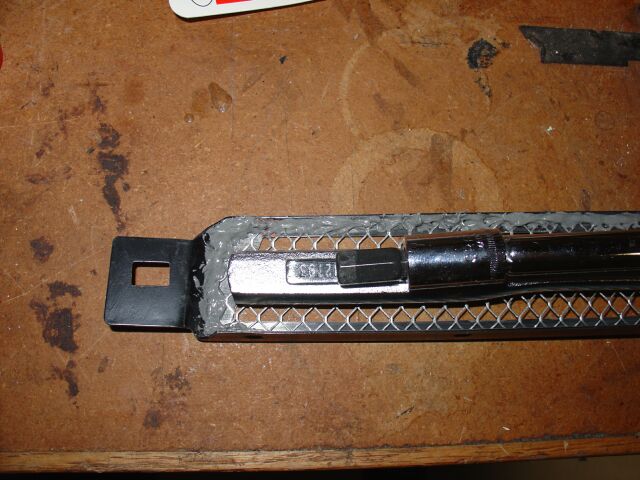 To
adhere the mesh to the panel, I chose to use JB Weld. With a batch mixed
up, it was carefully applied all along the edges of the mesh/panel. I used
some heavy sockets and wrench's to keep the mesh flush with the panel for the 10
hours of cure time.
To
adhere the mesh to the panel, I chose to use JB Weld. With a batch mixed
up, it was carefully applied all along the edges of the mesh/panel. I used
some heavy sockets and wrench's to keep the mesh flush with the panel for the 10
hours of cure time.
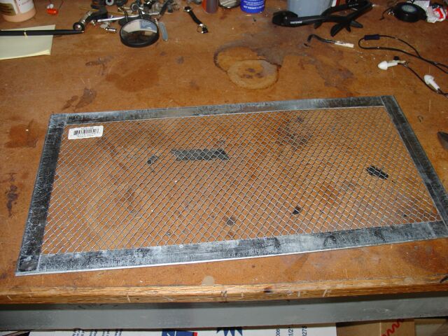
 This
is the other end of the panel with added weight to keep the mesh flush with the
panel.
This
is the other end of the panel with added weight to keep the mesh flush with the
panel.
 Here
is the panel the next day after the cure. Make sure you don't slop the JB
Weld on, otherwise it can get into your mesh openings, you don't want any of it
visible once the panel is installed. Using JB Weld, I will never worry
about the mesh coming unsecured.
Here
is the panel the next day after the cure. Make sure you don't slop the JB
Weld on, otherwise it can get into your mesh openings, you don't want any of it
visible once the panel is installed. Using JB Weld, I will never worry
about the mesh coming unsecured.
 While
I wait for the paint to dry, its time to take the existing panels off and prep
the area for the new vented panels. As for the painting, I used my trusty
rattle can of color matched Signal Red (www.towerpaint.com)
and after sanding with 400 grit and some spot putty, they were painted.
While
I wait for the paint to dry, its time to take the existing panels off and prep
the area for the new vented panels. As for the painting, I used my trusty
rattle can of color matched Signal Red (www.towerpaint.com)
and after sanding with 400 grit and some spot putty, they were painted.
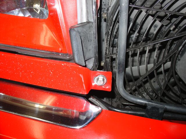
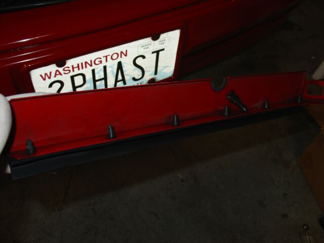
 The
side marker needs to be removed, then you will have access to the 10 mm nut
holding one end of the panel in place.
The
side marker needs to be removed, then you will have access to the 10 mm nut
holding one end of the panel in place.
 The
other 10 mm nut is accessed by opening the hood.
The
other 10 mm nut is accessed by opening the hood.
 With
the old panel off, you next need to remove the rubber trim attached to the
bottom. We will install this piece on our new panels.
With
the old panel off, you next need to remove the rubber trim attached to the
bottom. We will install this piece on our new panels.
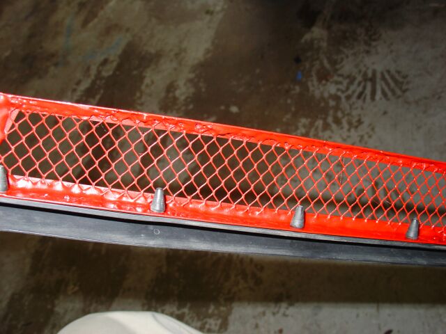 Here
is the bottom rubber gasket mounted to the new vented panel. The rubber
nubs were sticking up to far and were visible from the front, so something had
to be done!
Here
is the bottom rubber gasket mounted to the new vented panel. The rubber
nubs were sticking up to far and were visible from the front, so something had
to be done!
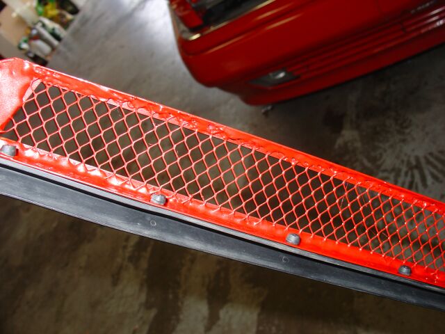 Next
was to cut these rubber nubs down so they are not sticking up and are visible.
They were also painted red to further blend in and not stand out.
Next
was to cut these rubber nubs down so they are not sticking up and are visible.
They were also painted red to further blend in and not stand out.
 This
rubber gasket won't be used with our new vented panels, so carefully remove it
and store it away with your original panels.
This
rubber gasket won't be used with our new vented panels, so carefully remove it
and store it away with your original panels.
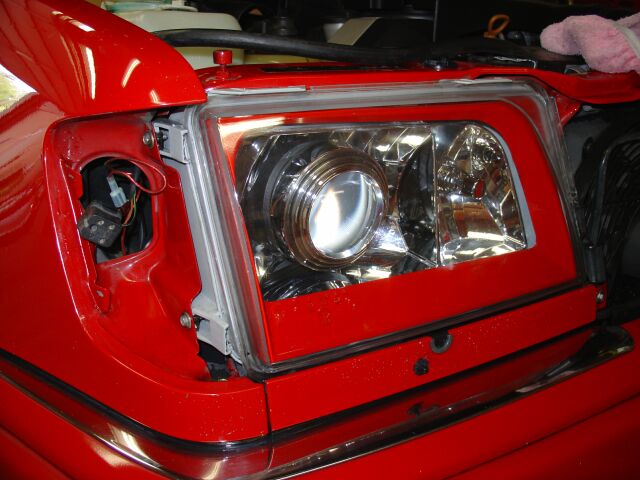
 Once
I had everything removed, I did a test fit of the panel and discovered that I
was able to see to much behind the panel. The bottom portion of the
headlight and the wiper motor mount in particular.
Once
I had everything removed, I did a test fit of the panel and discovered that I
was able to see to much behind the panel. The bottom portion of the
headlight and the wiper motor mount in particular.
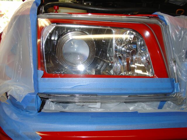 A
extra step that I had not anticipated, masking off the headlight and bumper area
so I could paint the bottom portion of the headlight and wiper motor mount,
black.
A
extra step that I had not anticipated, masking off the headlight and bumper area
so I could paint the bottom portion of the headlight and wiper motor mount,
black.
 You
can see that once painted black, these area almost disappear, this adds to
the cosmetic appearance of this particular modification.
You
can see that once painted black, these area almost disappear, this adds to
the cosmetic appearance of this particular modification.
 With
the painting done and the panel paint dry, it was time to install.
With
the painting done and the panel paint dry, it was time to install.
 The
finished product! Although it would be hard to measure the added
performance of this modification (especially since it really is only going to
work at speed) every little bit helps in getting more performance out our your
vehicle.
The
finished product! Although it would be hard to measure the added
performance of this modification (especially since it really is only going to
work at speed) every little bit helps in getting more performance out our your
vehicle.
 This
project turned out well and I really like how the vent openings follow the lines
of the headlights.
This
project turned out well and I really like how the vent openings follow the lines
of the headlights.
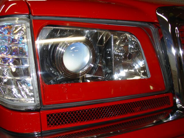 Another
picture of the finished product.
Another
picture of the finished product.
These videos cover the Hella Euro headlights and the updated vented wiper
panels.
K&N Air
Filter Installation - 6-7-06
 Continuing
the quest for every little bit of performance, the next item to upgrade is the
air filters. Its long been known that free flowing air filters can net you
a good increase in performance. (the upgraded air filter on my Corvette netted
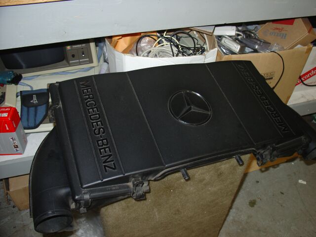
me 17 rwhp). So we start by removing the 500E airbox
Continuing
the quest for every little bit of performance, the next item to upgrade is the
air filters. Its long been known that free flowing air filters can net you
a good increase in performance. (the upgraded air filter on my Corvette netted
me 17 rwhp). So we start by removing the 500E airbox
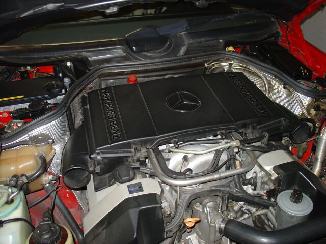 The
front plastic shield of the air cleaner assembly lifts off, then we remove the
two air intake pipes. The air cleaner assembly lifts up from the front,
then you slide it towards you.
The
front plastic shield of the air cleaner assembly lifts off, then we remove the
two air intake pipes. The air cleaner assembly lifts up from the front,
then you slide it towards you.
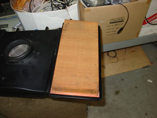
 With
the air cleaner assembly off, we need to flip it over and release several clips
on each side. We can then remove the plastic cover exposing the air
filters
With
the air cleaner assembly off, we need to flip it over and release several clips
on each side. We can then remove the plastic cover exposing the air
filters
 With
the clips released, the bottom cover (one over each filter) lifts off.
With
the clips released, the bottom cover (one over each filter) lifts off.
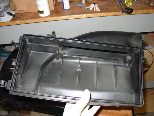 This
is the cover that was just removed, now is a good time to clean up your air
cleaner assembly, both inside and out.
This
is the cover that was just removed, now is a good time to clean up your air
cleaner assembly, both inside and out.
 This
picture gives you an idea of the air flow through the air intake.
This
picture gives you an idea of the air flow through the air intake.
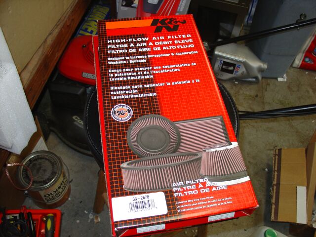 Of
course, my favorite choice of performance filters is K&N. They have always
netted a good HP increase and have never let me down. For the 500E, you
need two of these. Your local auto parts store should be able to order
them or you can get them from EBay for around $35 each.
Of
course, my favorite choice of performance filters is K&N. They have always
netted a good HP increase and have never let me down. For the 500E, you
need two of these. Your local auto parts store should be able to order
them or you can get them from EBay for around $35 each.
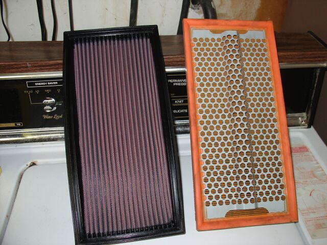 This
is the K&N next to the OE filter
This
is the K&N next to the OE filter
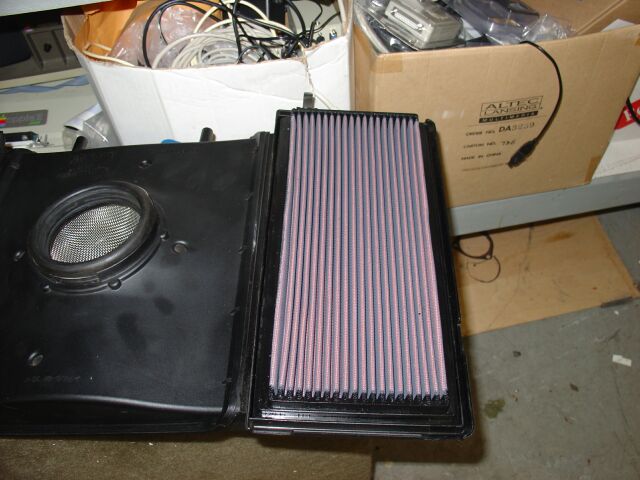 Installation
is simple, they just drop in. After about 10,000 miles +/-, you need to
remove the filters and using the K&N cleaning kit, clean and then re-oil the
filters. You should always oil the side of the filter that faces the dirt
(air coming in) and oil "lightly". Many people over oil these filters and
this can lead to fouling of the HFM and/or MAF with oil. Done correctly,
you should never have to worry about this kind of problem happening to you.
Installation
is simple, they just drop in. After about 10,000 miles +/-, you need to
remove the filters and using the K&N cleaning kit, clean and then re-oil the
filters. You should always oil the side of the filter that faces the dirt
(air coming in) and oil "lightly". Many people over oil these filters and
this can lead to fouling of the HFM and/or MAF with oil. Done correctly,
you should never have to worry about this kind of problem happening to you.
<Back
Information/pictures on this site are the property of Rik Johnson and are not
to be used without written permission.