Audio Upgrades
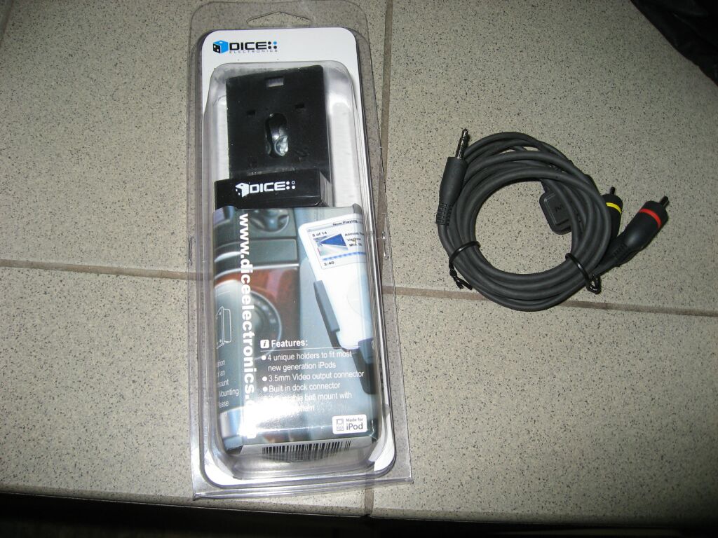 I used a Dice Electronics Ipod mount for my 5th gen Ipod Video. This mount allows charging and also video output. Cost is around $50 depending upon where you purchase it from.
 You can see the Ipod mount taken apart for mounting. It is being mounted onto a Cuda leather mount, which sits on the right side of the factory radio. The Ipod mount has a 90 degree ball pivot which allows you to angle the Ipod towards the driver for better visibility. A OE Apple Ipod charger and AV cable are utilized during this installation.
 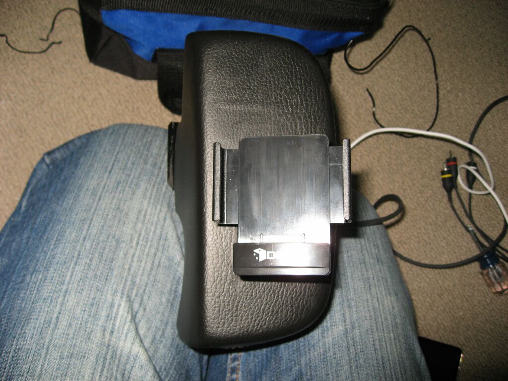 Another picture of the fully installed Ipod mount before installation into the CLK.
 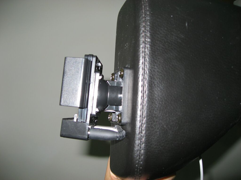 This angle shows the pivot mount and how I routed the charging cable and AV cables inside of the Cuda mounting base.
 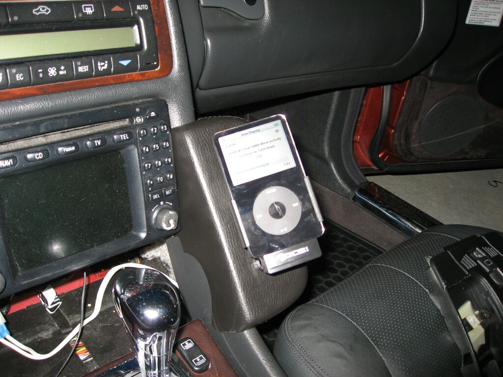 This is the Ipod mount installed and you can see how the Cuda mount fits onto the center console of the CLK. No cutting or screws are needed, but there is a clip that snaps in behind the lip of the Comand radio. The AV inputs are routed into the AV1 inputs of the Euro TV tuner (more on that later)
At this point, I do not have many pictures of the audio system, but a quick summary. Euro Comand radio, programmed for "Video in motion" and connected to the Comand is the TV tuner shown. The TV tuner is a euro only option, so because it is PAL, it does not work correctly in the US, but it does give you two AV inputs. In my system, I use AV1 for the Video Ipod and AV2 is connected to a six disc DVD changer, this is in addition to the factory six disc CD changer.
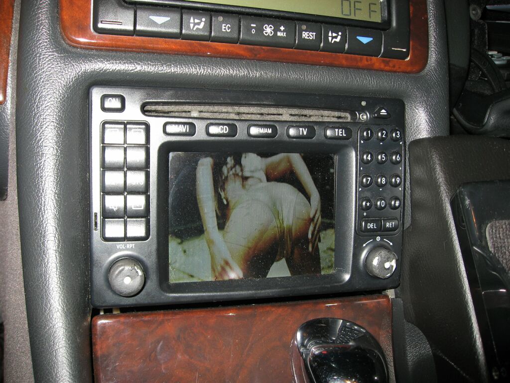 This is the Euro Comand playing a music video. The knobs need replacing, which is another project coming up. I ordered knobs from Germany, as MB dos not offer this replacement items. The main difference between the US Comand the Euro is the ability to plug in a TV tuner and play videos (like shown). There are also problems with the AM section of the radio. US Navigation discs work just fine and so do all other functions.
It took a while for the knobs to arrive from Germany, as they were on back order. They were not cheap, around $15 euro each plus shipping. Here you can see the existing knobs and their current state of deterioration.
 These
are the new knobs. The Comand is a nice design, over engineered, so
replacement of the knobs is not just a simple matter of pulling off the old
ones and pushing on the new ones. You need to remove the entire face
of the Comand to do this.
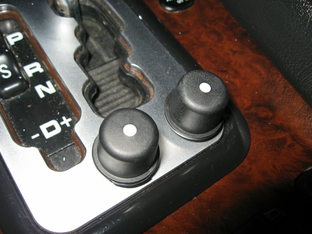
These
are the new knobs. The Comand is a nice design, over engineered, so
replacement of the knobs is not just a simple matter of pulling off the old
ones and pushing on the new ones. You need to remove the entire face
of the Comand to do this.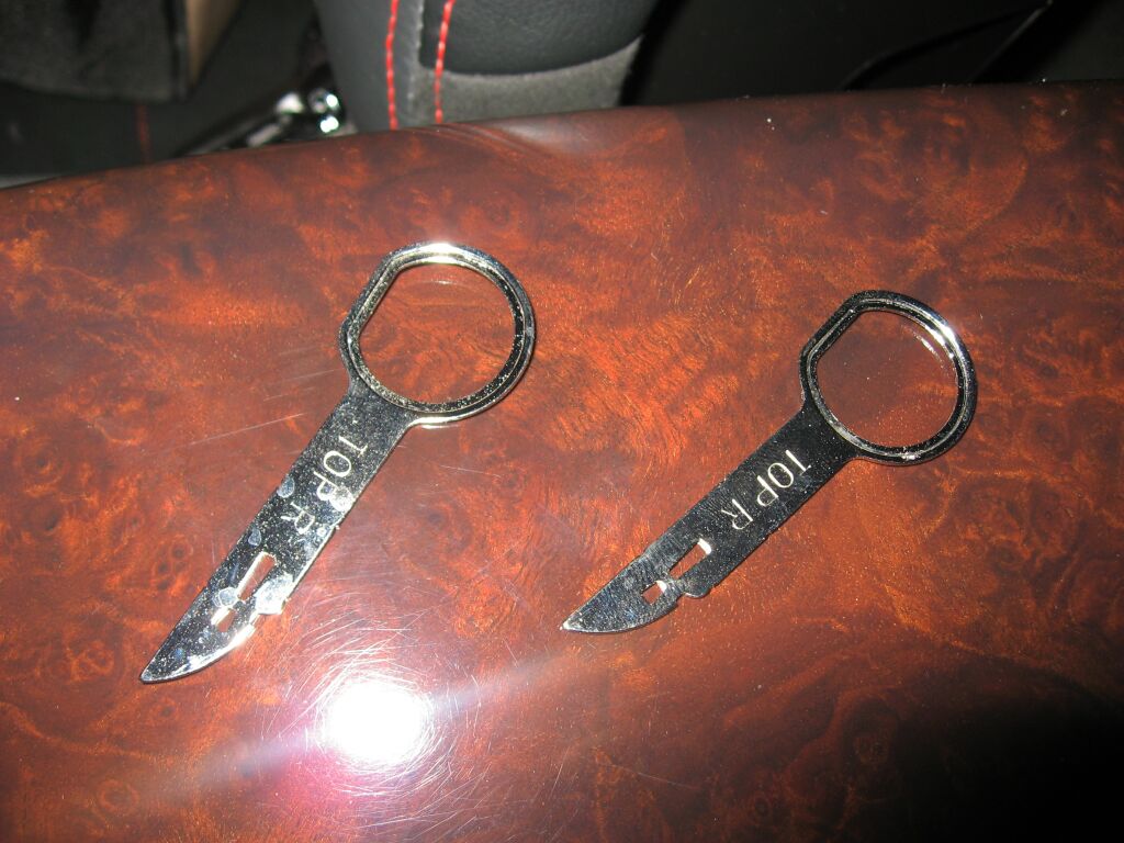 To
remove the radio, you need a set of these removal keys. I picked these
up off of Ebay, but you can also purchase through the dealer. These
keys are also used to remove the climate control system. Make sure you
purchase the keys with the notches on them, the keys are also available
without the notches, and these won't work.
To
remove the radio, you need a set of these removal keys. I picked these
up off of Ebay, but you can also purchase through the dealer. These
keys are also used to remove the climate control system. Make sure you
purchase the keys with the notches on them, the keys are also available
without the notches, and these won't work.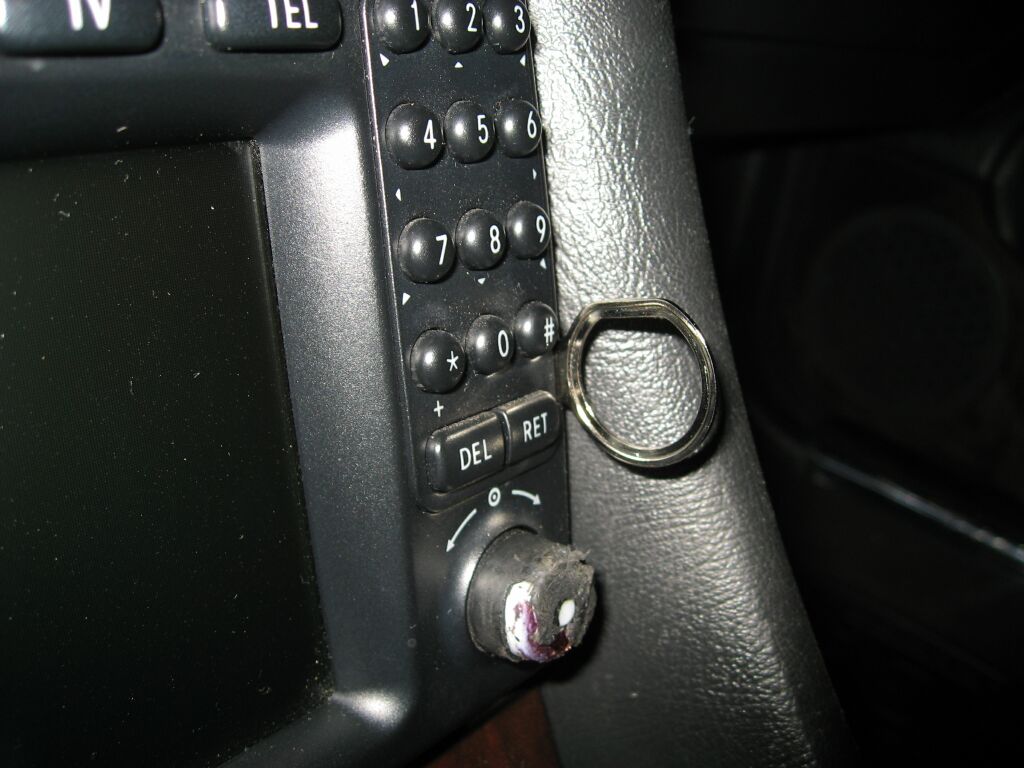 When
you insert the keys, they will snap into place, then you just pull the radio
out.
When
you insert the keys, they will snap into place, then you just pull the radio
out.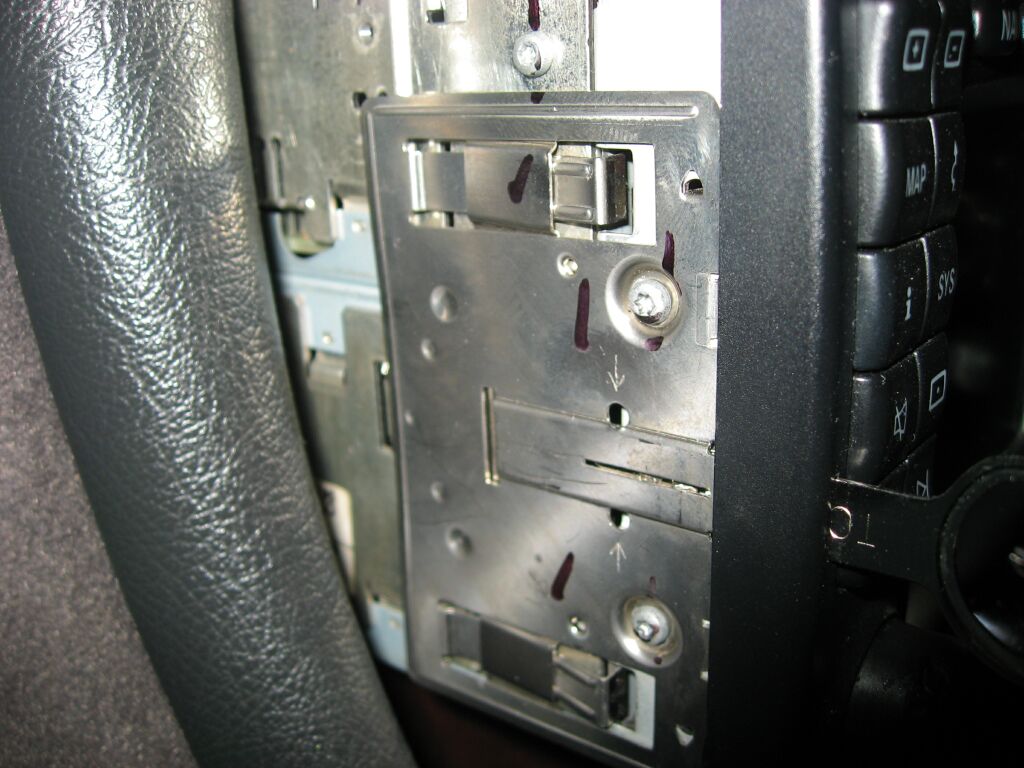 For
this project, I don't need to remove the entire Comand unit, just pull it
out far enough so I can access the Torx screws on either side. To
remove your keys, you insert a small flat blade screw driver into the hole
(indicated by the arrow) and push inward, you should then be able to remove
the key. Next you need to remove this bracket, so remove the two Torx
screws shown here.
For
this project, I don't need to remove the entire Comand unit, just pull it
out far enough so I can access the Torx screws on either side. To
remove your keys, you insert a small flat blade screw driver into the hole
(indicated by the arrow) and push inward, you should then be able to remove
the key. Next you need to remove this bracket, so remove the two Torx
screws shown here. Once
the mount bracket is removed, you have two more Torx screws on each side of
the radio that need to be removed. Once removed, you can remove the
entire face of the Comand.
Once
the mount bracket is removed, you have two more Torx screws on each side of
the radio that need to be removed. Once removed, you can remove the
entire face of the Comand. Once
the screws are removed, the face of the Comand will pull straight off.
Once
the screws are removed, the face of the Comand will pull straight off. This
is the back side of the Comand face. We need to take this apart also.
There are four small Torx screws that need to be removed
This
is the back side of the Comand face. We need to take this apart also.
There are four small Torx screws that need to be removed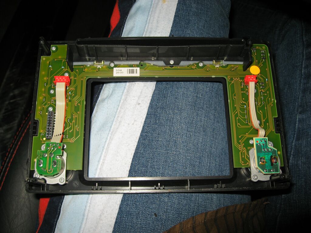 Once
the Torx screws are removed, you can remove the front plastic assembly.
Remove it by pulling gently away from the frame. These pieces are
connected together by the pin block (shown in the left side of this
picture), do not pull at an angle as you don't want to bend or break off any
of these pins. Next, you need to remove all of the Torx screws on this
circuit board and the Torx screws holding the adjustment pots in place,
there are +/- 16, make sure you get them all, some are hidden under the
ribbon cables.
Once
the Torx screws are removed, you can remove the front plastic assembly.
Remove it by pulling gently away from the frame. These pieces are
connected together by the pin block (shown in the left side of this
picture), do not pull at an angle as you don't want to bend or break off any
of these pins. Next, you need to remove all of the Torx screws on this
circuit board and the Torx screws holding the adjustment pots in place,
there are +/- 16, make sure you get them all, some are hidden under the
ribbon cables.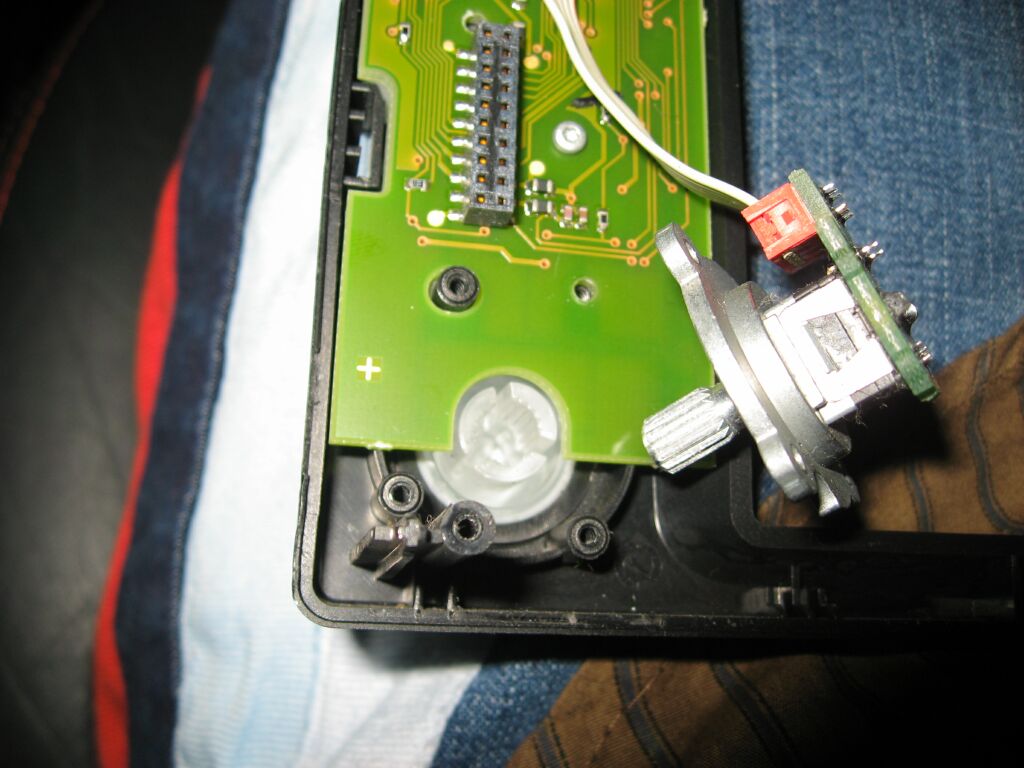 Once
all the Torx screws are removed, carefully pull out the adjustment pots like
shown
Once
all the Torx screws are removed, carefully pull out the adjustment pots like
shown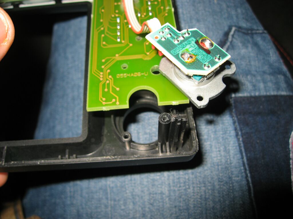 Now,
lift up the circuit board just enough so you can remove the knobs, don't
remove the circuit board. Also, don't turn it upside down, you don't
want to dislodge the buttons. Now, you can install the new Comand
knobs, and put the adjustment pots into the new knobs (don't force them,
rotate them till they slip into place). Now you can re-install all the
Torx screws and put the Comand back together.
Now,
lift up the circuit board just enough so you can remove the knobs, don't
remove the circuit board. Also, don't turn it upside down, you don't
want to dislodge the buttons. Now, you can install the new Comand
knobs, and put the adjustment pots into the new knobs (don't force them,
rotate them till they slip into place). Now you can re-install all the
Torx screws and put the Comand back together.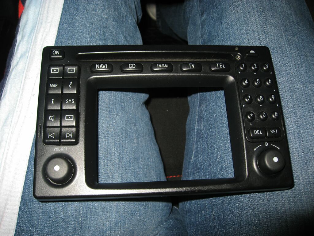 Once
all the Torx screws are put back, its best to check to make sure all the
buttons are in place and work.
Once
all the Torx screws are put back, its best to check to make sure all the
buttons are in place and work.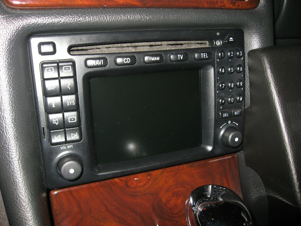 Before
I actually put the Comand completely back together and pushed back into the
dash, I checked all button functionality. Which is a good idea, just
to make sure something did not become un-seated while you were working on
it.
Before
I actually put the Comand completely back together and pushed back into the
dash, I checked all button functionality. Which is a good idea, just
to make sure something did not become un-seated while you were working on
it.MB Factory Phone System Upgrade
The 2000 CLK originally came with a StarTac phone system, so for many years there was no solid upgrade path, except to upgrade to a V60 phone system. That required a different phone/cradle and a different PSE (phone controller). After a few years, even that became outdated, so Mercedes answered the call and came out with a V60 bluetooth puck, which is a bluetooth module that takes the place of the V60 phone. This allows you to use almost any bluetooth enabled phone and have full access to the phone/phonebook through the steering wheel and Comand System.
 This is the center console tray removed. To install the new cradle, you need to remove the four screws at the bottom. This seperates the top portion of the tray from the bottom portion. If your going to do this upgrade, you will probably take the tray apart while it is still mounted in the vehicle.
 This is the tray with the top portion removed. The cradle coiled cord and the Teleaid cord pass from the top portion of the tray, down through the opening shown and then plug into the harness in the bottom of the center console.
 This is the top portion of the tray, I have already removed the StarTac cradle (you can see the outline) and will mount the V60 cradle in this general area to cover up the left over holes as much as possible.
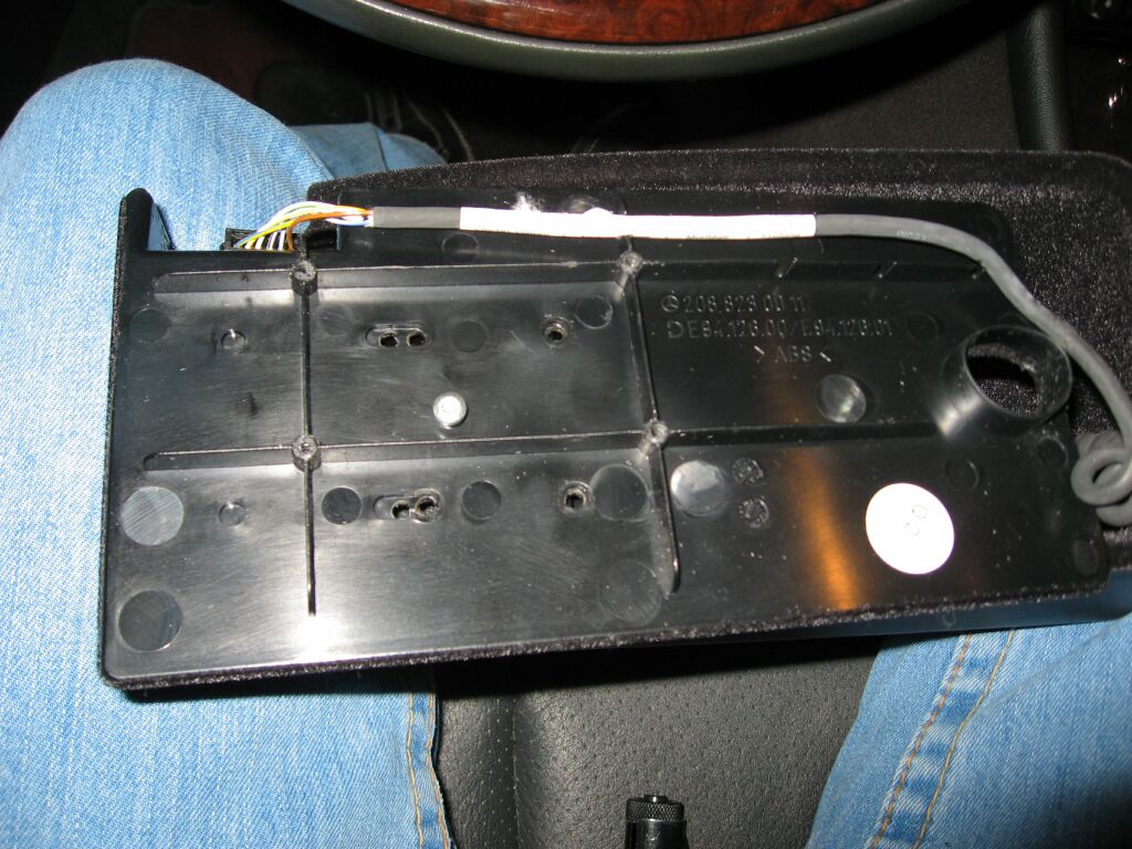
This is the underside of the top portion of the tray, the wires shown route from the Teleaid buttons.
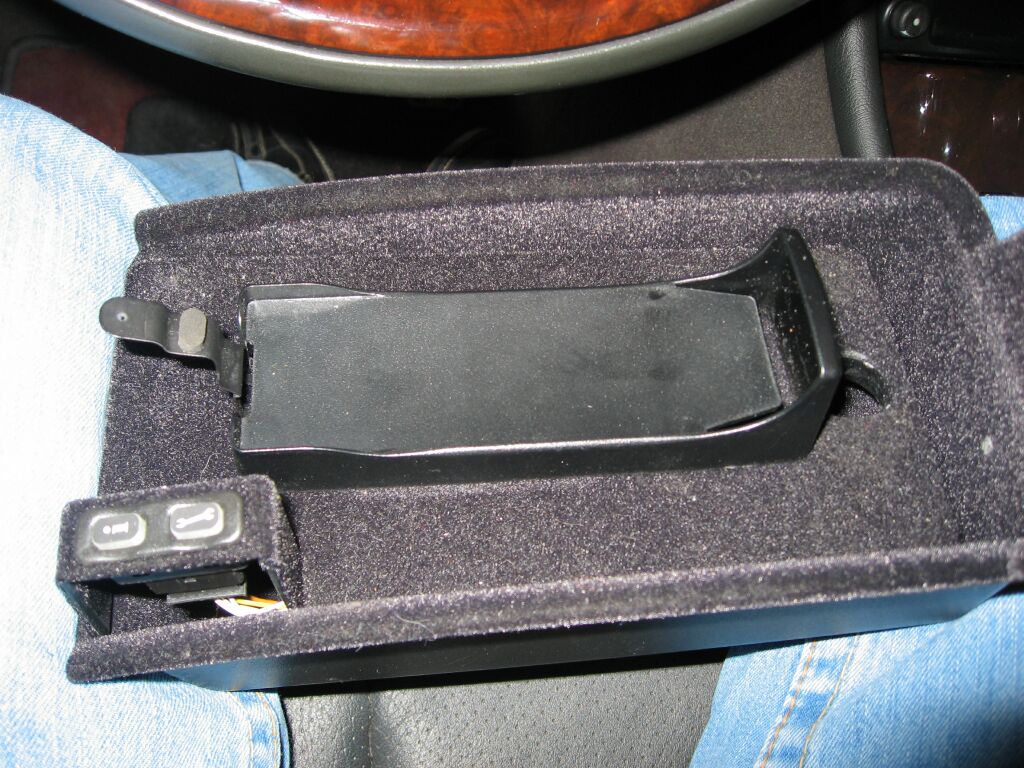 Here you can see the V60 cradle base mounted. (The V60 cradle is a two part item, the mount shown and the actual cradle).
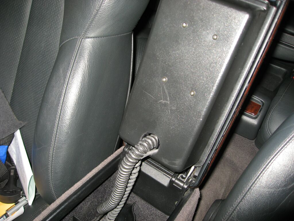
 Inside the center console, you need to remove a small piece of carpet to gain access to one screw. This screw holds the plastic shield (shown here) in place. You will need to unplug the StarTac cable and plug the V60 cradle in. The antenna portion just unscrews. This is the DB2 system, which was in the Mercedes vehicles from 2000-2005, you can easily identify what you have by the connector, in DB2 vehicles it is a RJ45 jack, which looks like a large plug plug like you have on your home phone. You won't have the cig lighter here, mine was relocated.
 Once the cables are plugged in and the snap grommits put back, you can put your plastic guide cover back and secure with the single screw. Make sure your cables are not kinked and the tray closes/opens without binding or pinching your wires.
 This picture shows the small piece of fitted carpet that is re-installed.
 Here we see the center tray re-insalled as I test the opening/closing and verify the cables don't get binded or pinched in any way.
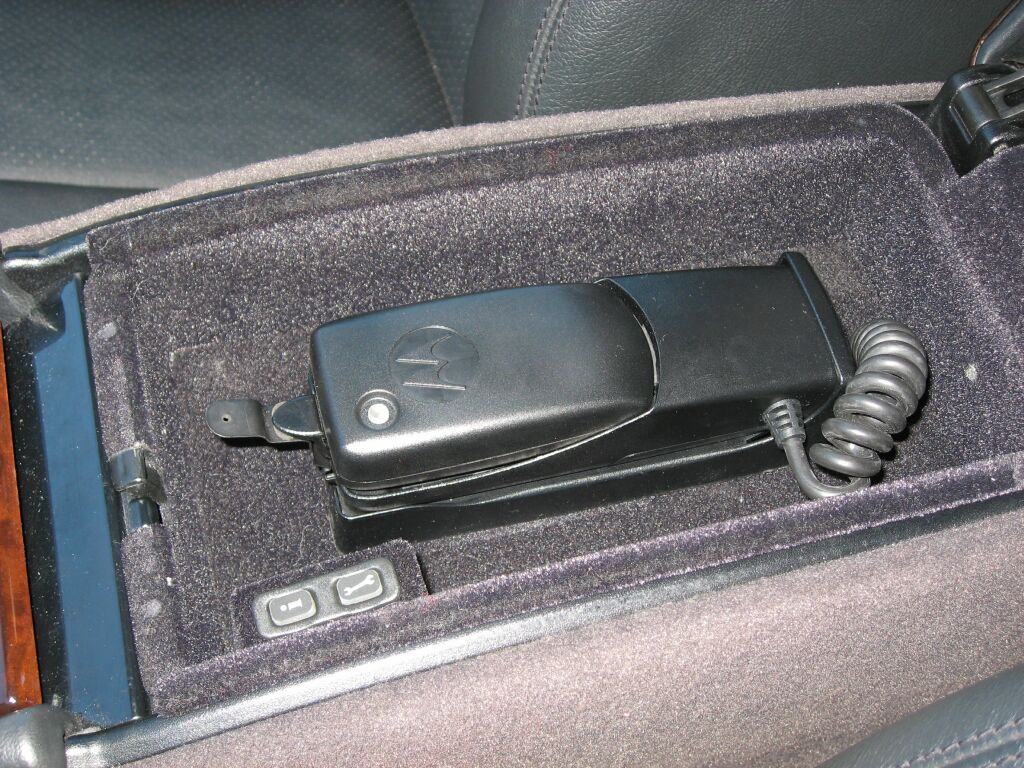
The Bluetooth puck is shown installed in the first picture. I don't have pictures of the PSE or VCM installation, but these items are located behind the drivers side panel in the trunk. You need a blue label PSE for this upgrade. The StarTac PSE has a white label on it. Be sure to check my technical documents section, as I have MB installation instructions for the phone installation located there. The MB instructions are much more detailed than mine and contain part numbers.
Passport SR7 with SRX Laser Shifter Installation
 For this car, I purchased a Passport SR7 with SRX Laser shfiters, it includes two front mounted laser shifters, one rear mounted laser shifter and the front mounted radar unit. It is a complicated installation, but worth it if you want complete stealth and no bulky windshield unit screaming "steal me". This picture shows the underside of the front bumper and one laser shifter installed to the far right.
 This is a view from the front of the bumper and you can see the laser shifter though the bumper slats. The Lorinser bumper normally has mesh covering these slats (not unlike the mesh used on the rear bumper) but for the detectors, the mesh needed to be removed.
 The other front mounted laser shifter was mounted to the far left.
 Here you can see the front radar unit mounted off center and close to the right laser shifter. Although Passport recommends this unit be mounted in the center of the two shifters, my front license plate is in the way. All sensors need a clear view to the road to be effective and cannot be hidden behind the bumper or any metallic object. All the wires were secured and routed to the drivers side and up into the engine bay near the headlight.
 Here is the front detectors wiring pulled up and into the engine bay by the ABS pump.
 After un-wrapping all the cable, they were all protected using split loom tubing and routed safely up to the fuse box.
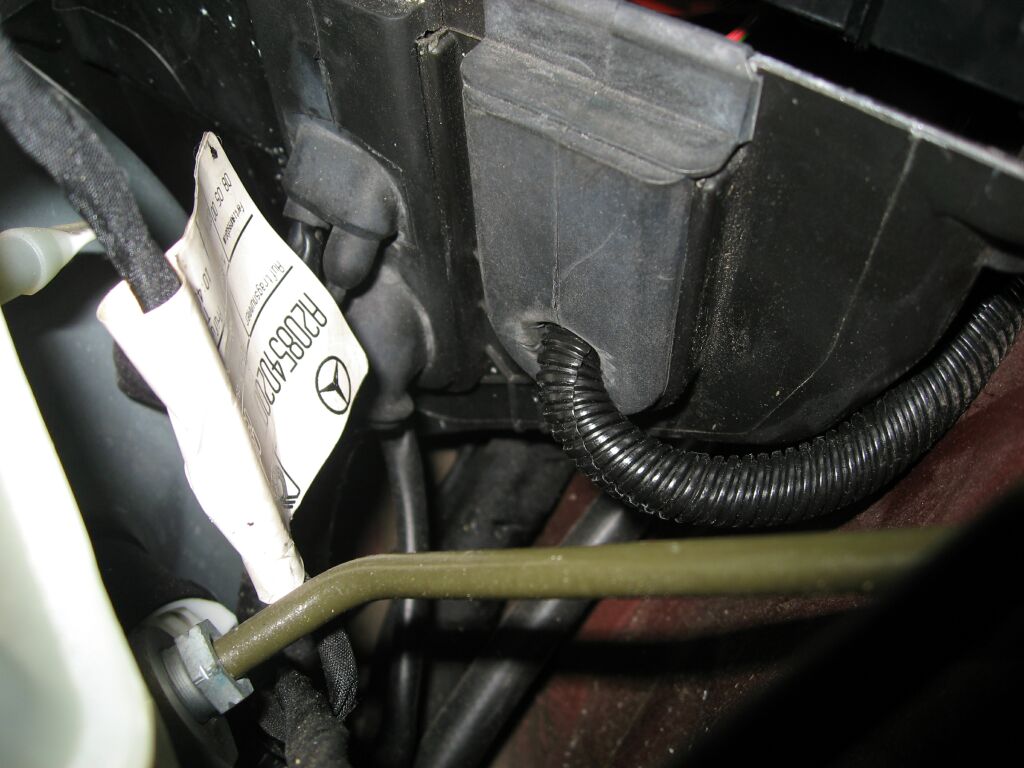
 I removed the washer tank to gain better access to the sub-firewall and used a factory, grommited location to route my loom tubing
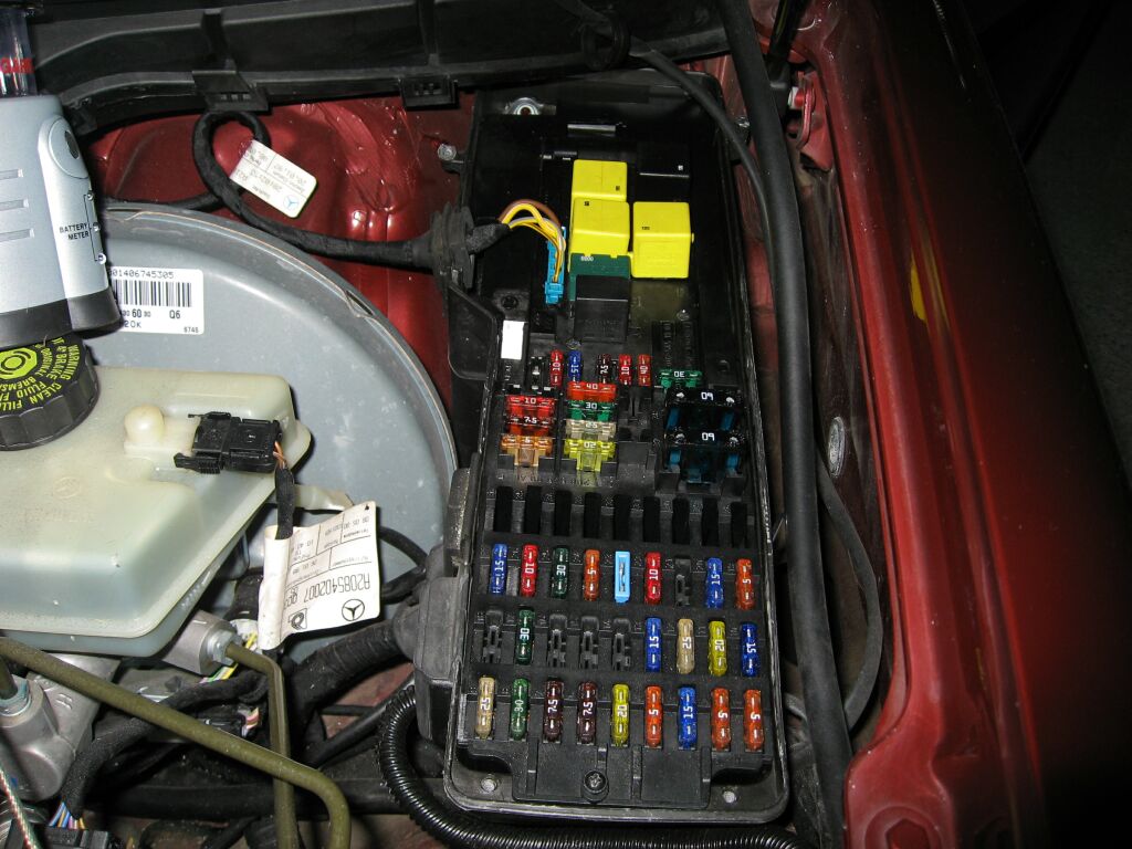
 The goal was to route the loom into the engine fuse block and then into the drivers side footwell. Of course you need to take the whole fuse block apart and there are a few screws holding the top assembly in place. On the side, there was a unused grommit (seen sitting on top of the fuse block) which will be utilized to route the loom into the fuse box, along the length of the box and down into the footwell.
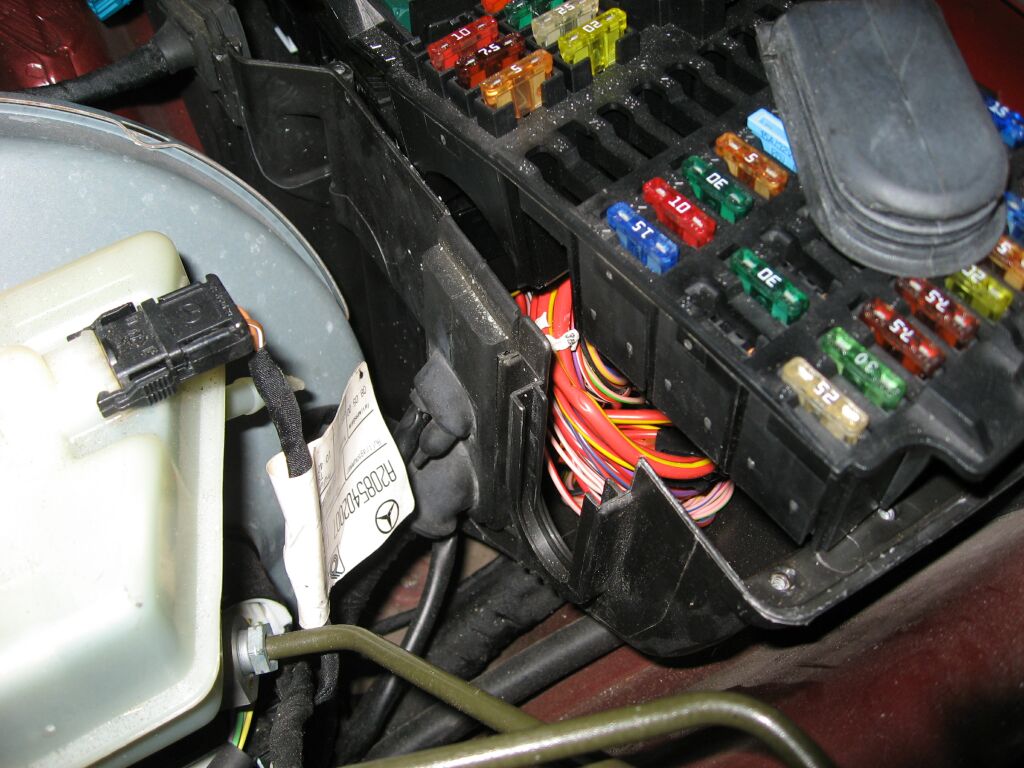 You don't need to move the top of the fuse box very far, just enough to free up space to route your wires.
 I used a knife to cut a circular hole, just a bit smaller than the loom, this will create a nice water tight seal. A dab of silicone to the rear ensures that no water gets into the fuse block assembly.
 You can see the loom route up past the relays and down into the drivers footwell area. This is the area I chose to locate ground, power and mount the hub of the Passport. Because of the nature of this particular installation, I am using a on/off toggle switch mounted under the drivers side of the dash to turn the Passport on/off.
 At this point, all that is left to do is put the fuse block back together, do some misc. clean up and procede to the next phase of the installation.
 The rear laser shifter will be mounted over the top of the license plate. So we need to remove the inner trunk liner for routing of the wires. Push pin clips hold this liner in place and it comes off easy.
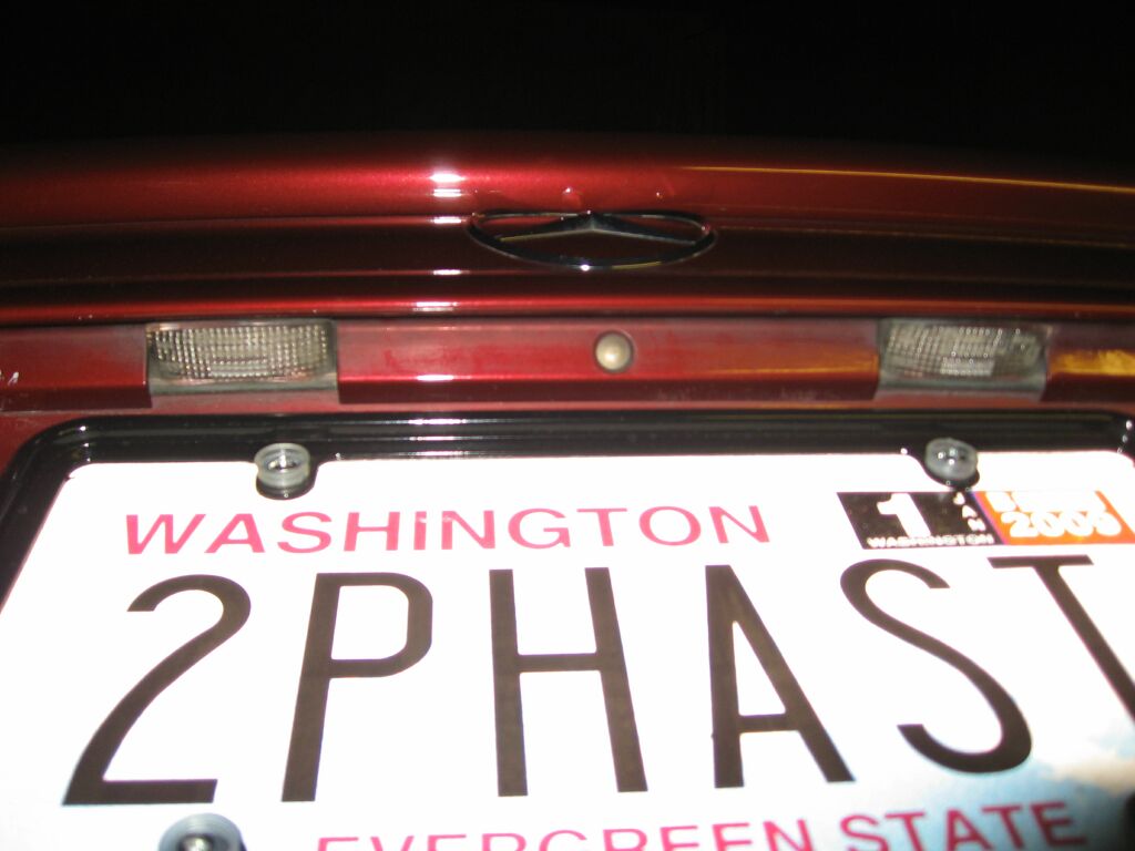
I chose to mount the laser shifter between the two license plate lights, this shouldn't interfere with changing the bulbs
 A hole needs to be drilled for the supplied rubber grommit, make sure to choose a location that has nothing important behind it and is actually under the license plate.
 This is the laser shifter installed (using two sided tape) and the wire routed and grommitted. The item located to the right and the smaller item located to the left are a color CCD backup camera and microphone, which are not utilized. While a novel idea, they are just not practical for day to day use.
 The main controller for the Passport is a smaller box with LED display. For this installation, the LED display was removed and extended, this would facilitate installation inside of the rear view mirror. So we start with removing the mirror, mounting the controller and routing the LED display. Its also good to verify that everything works as it should. The Passport uses RJ8 mini plugs and these things easily get damaged.
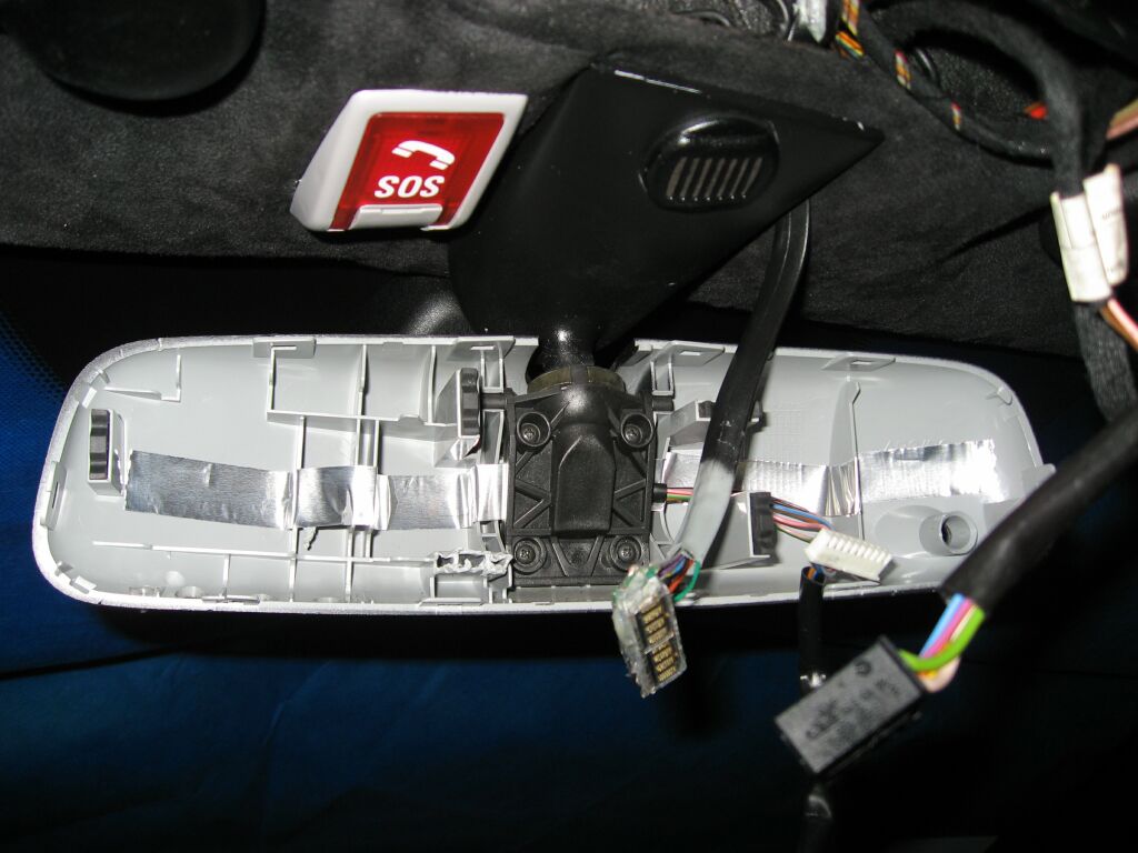 Once the controller is mounted, I reinstalled the dissassembled mirror frame, this holds the LED cable in place, as the next step will be to secure the LED to the inside of the mirror. I chose to use a combination of silicone and tape. This ensures that the display does not move around while the silicone cures.
 The reflective material on the back of the mirror needs to carefully removed. A razor blade is handy to acclomplish this. Your cut-out should be the same size as the LED display.
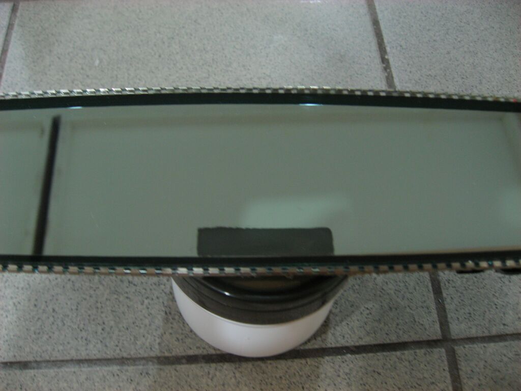 You can see the cut out from this front view. Be carefull not to scratch the inside of the mirror
 Once you are ready, you need to secure the LED to the back of the mirror. I actually suspended the mirror from the headlinger using wire, then positioned the LED in place, put a bead of silicone around it and then overlaid it with several strips of duct tape. Verify LED position placement before the silicone cures. Once done, you can reassemble the mirror. Make sure the mirror is plugged into its harness and if you took the Homelink controller out, make sure that is plugged back in as well. I verified everything was functional before I snapped the bezel trim back onto the mirror.
 This is a better daytime picture of the mirror and the diplay. With the main controller mounted inside the headliner, you no longer have easy access to program the Passport, so you should program it before you mount it. Also mount it so the piezo speaker fires downwards. I took out a small plug in the overhead control panel, so that the sound better penetrates the cabin. The mute buttom mutes the unit and also controls volume.
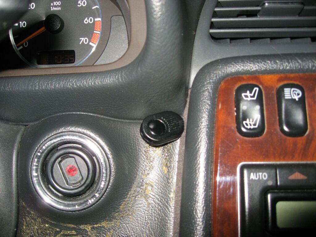 I chose to mount the mute buttom within easy reach, so I routed the wires down through the headlinger and A pilar, under the dash and up to this location. I used the supplied two sided tape to mout it here. This picture does not show the final mounting location, as I needed to clean off some glue from this area. The glue was left over from a crappy wood kit that was installed.

<Back
Information/pictures on this site are the property of Rik Johnson and are not to be used without written permission.